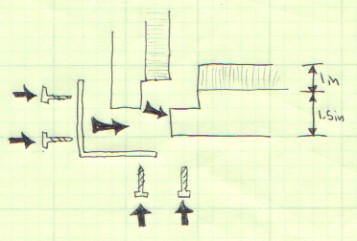
The dimensions provided below will give you a place to start with
the cornering and joining of your rack boards but length will ultimatly
depend on the size of your vacuum box
and its table top whos size
depends directly on the size of cookign sheed used for its construction.
|
|
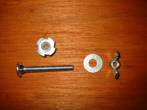
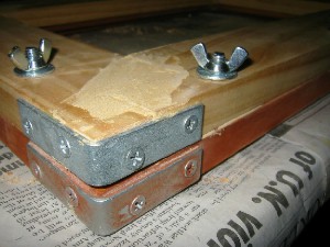
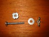
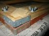
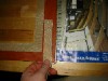
The hardware used in to lock the frames together is pictured
left. A 2.5in X 0.25in bold is recessed into the bottom frame.
For added strength a recessed threaded 0.25in well has been
fitted into that frame. The top fram has been drilled to allow
the bolt to pass though it and be secured by a 0.25in washer
and wingnut.
|
|
|
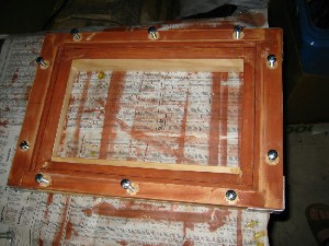
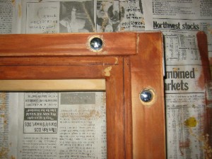
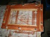
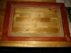
Bolt placement in the bottom rack is shown left. Ten bolts are
used to lock the frames together. the outer bolts on each board
were placed 2.5in from the edge of the boards.
|
|
|
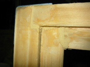
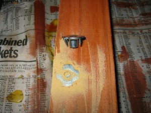
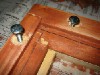
To recess the metal wells a hole for the well shaft was first
drilled all the way through the board. Then a hole with a larger
diameter then the well was drilled part way into the board. The
well has metal prongs on it which are designed to be pressed into
the wood arround the well. The well was then placed in the guide hole
and wodded blocks and a vice were used to press the well flush with
the rack surface. The unused hole area arround the well was then filled
with putty and sanded.
|
|
|
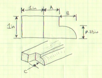
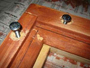
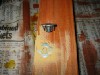
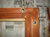
On the side of the bottom rack piece opposite the metal wells a hole
wider then the shaft of the bolt has been drilled to fully acomodate the
head of the bolt. When finished the rack top mates with the base through
the 10 connecting bolts and is held in place by wing nuts.
|
|
|
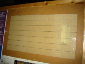
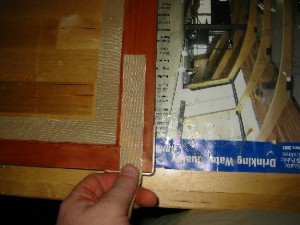
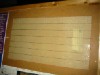
In order to provide a seal betweene the rack and the
table top and a
high traction surface betweene the racks and the plastic
I used strips of silicon sheeting tacked down to the frame.
|
|
|
To obtain the sheeting I used a silicon baking mat cut to produce
an o-ring for the bottom rack and a series of one inch wide strips
to cover the inter rack surfaces.
|