My Pony CNC Mill


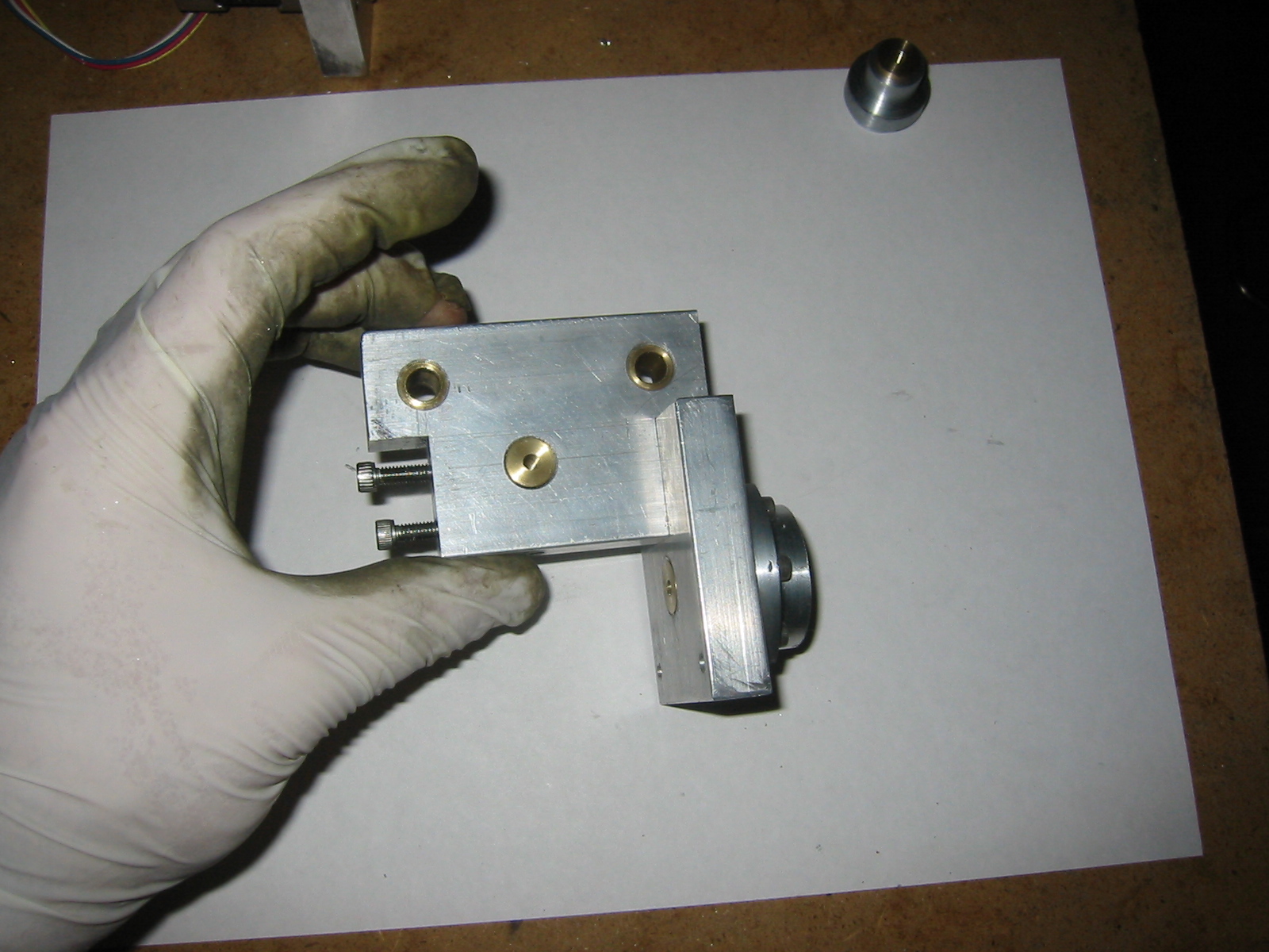
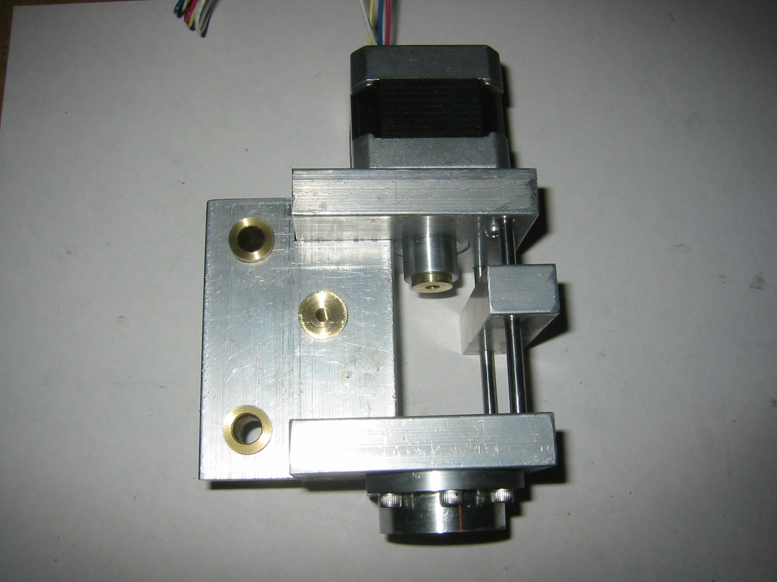
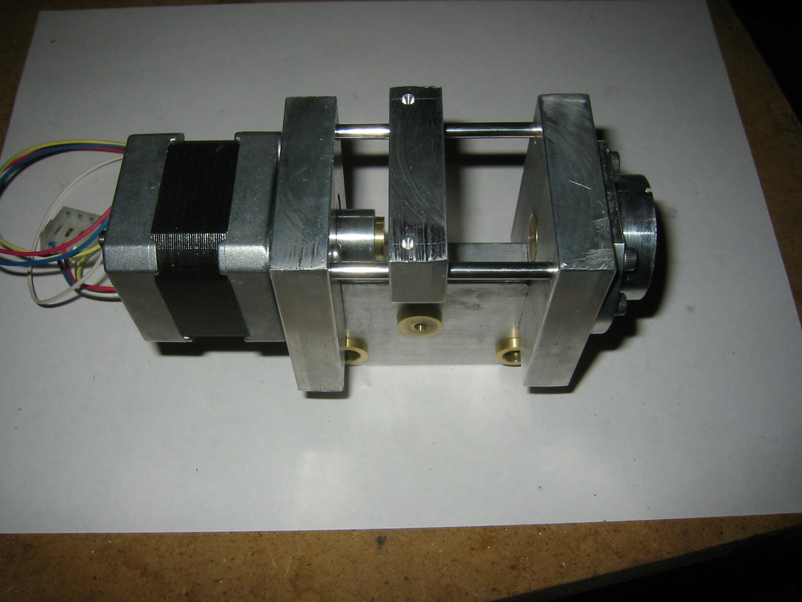
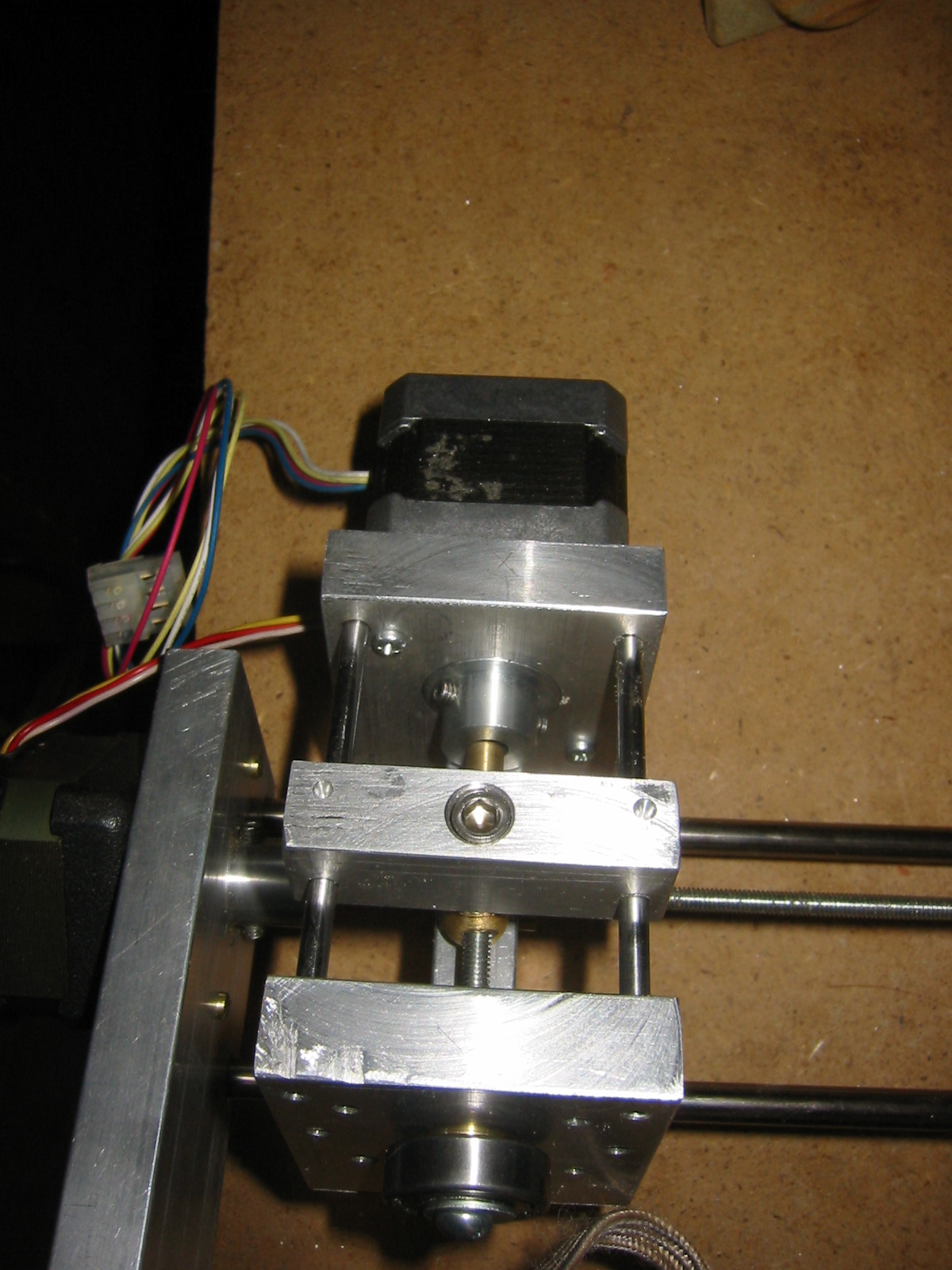
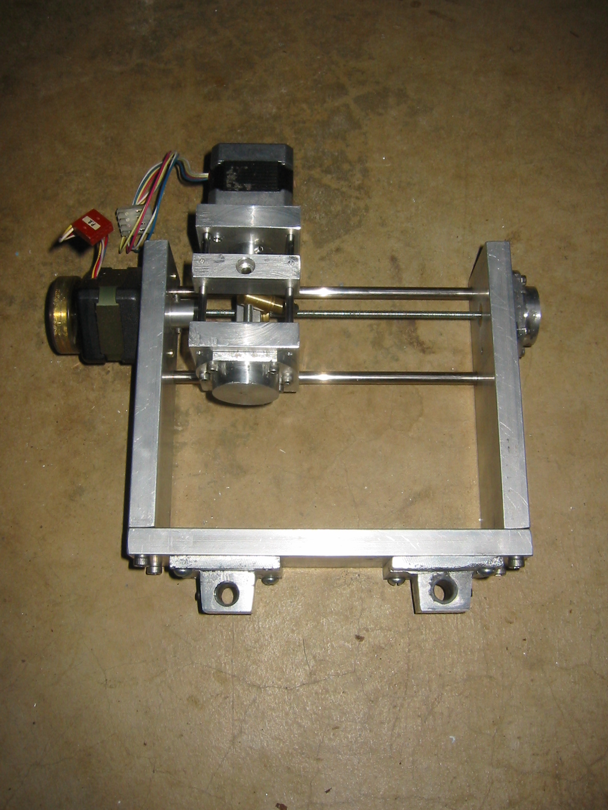
As you can see in the picture to the left the Z axis is built into a carriage that slides 'back and forth' along the Y-axis. Because I used such chunky Aluminium stock for the axis I really should upgrade the motor driving the Y-axis shuttle. Since I am upgrading the linear bearings to store bought ones I will need to redesign the Z-axis. Right now it is build right into the Y-axis carriage, which contains my homebuilt bearings. Once I have redesigned (and built another) Z-axis I will start looking at upgrading the Y-axis motors.

Ok, that last part is a lie, by that point I should have graduated and I will be looking at building an entirely new mill from scratch. I you have some money to throw at the problem you can make a crazy small CNC mill.

The Z-Axis

I built the Z-axis carriage by carving into the Y-axis shuttle.

The pin was lathed from brass bar stock. It is ugly but the whole idea was something I knocked up to test. I lathed the pin to shape, then drilled and tapped either end of the pin. Once that was done I milled a flat side into the pin through which the threaded rod would drive the pin along the Z-axis.

The picture left shows the Z-axis carriage before I drilled it for the pin.

My design for the Z-axis was by no means informed. I had read a lot about CNC milling machines, especially homebuilt ones, before starting this project. Problem was this was not only my first CNC mill but also my first project using a lot of these skills and ideas. Driving the Z-axis through an offset pin was not something I would do again. It is not as tall as a gearbox less design has the motor axis directly above the driving threaded rod. The problem is that with only two rods axis the off axis load is not the way to drive the Z-axis. Basically it tries to lock up the axis while it is being driven.

The picture to the left shows the pin connecting the Z-axis threaded rod connected to the Z-axis mounting point via the pin.


Email -- joeboy @ hhhh.org
Back to my home page.