|
|
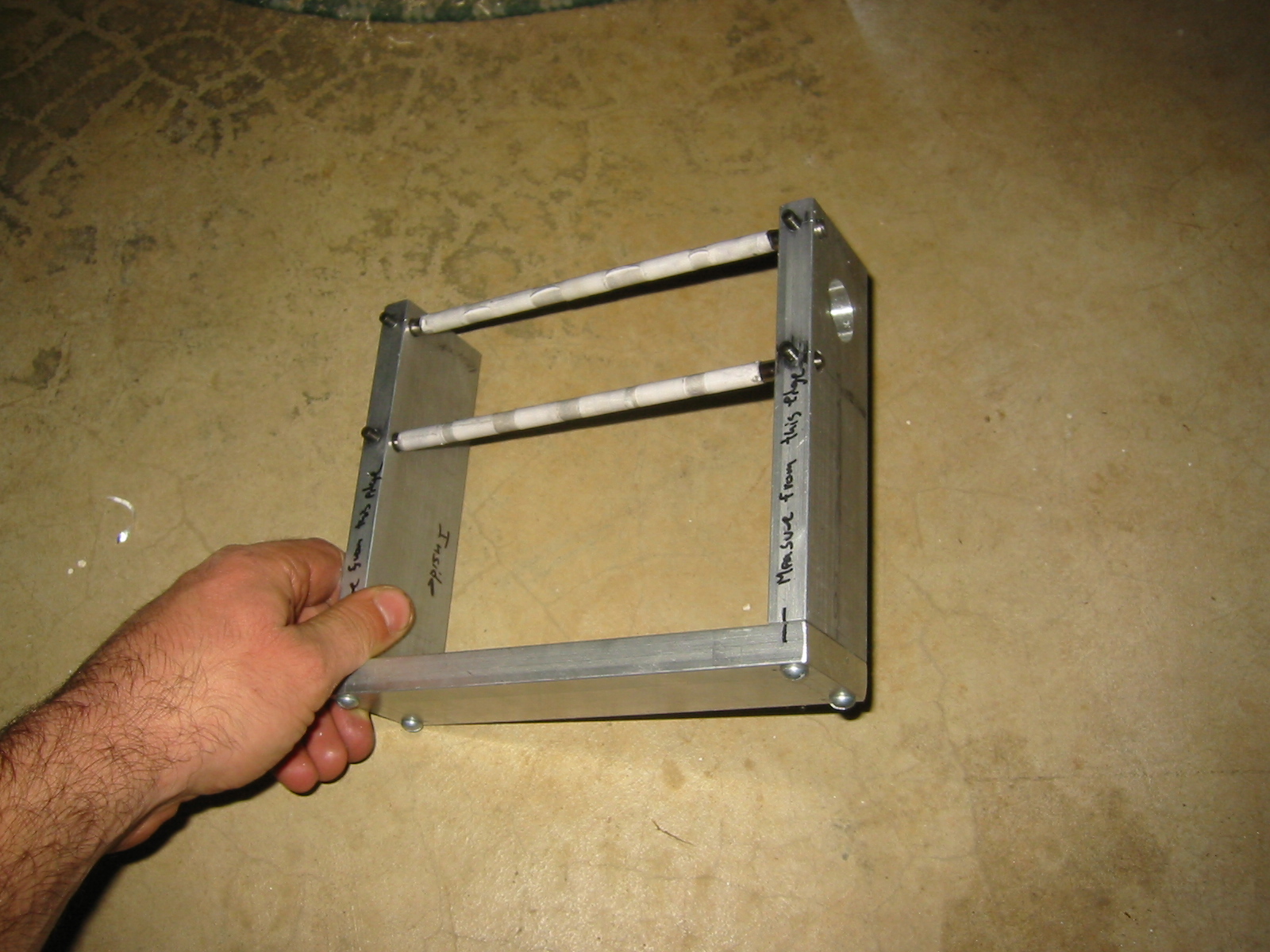
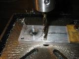
In order to drill the sides I marked, center punched,
center drilled, then step drilled the holes. All in all a
lot of work and I was still 1/1000 th of an inch off. I
need to practice this a lot more. Problem is I am really
not sure what I am doing wrong.
|
|
|
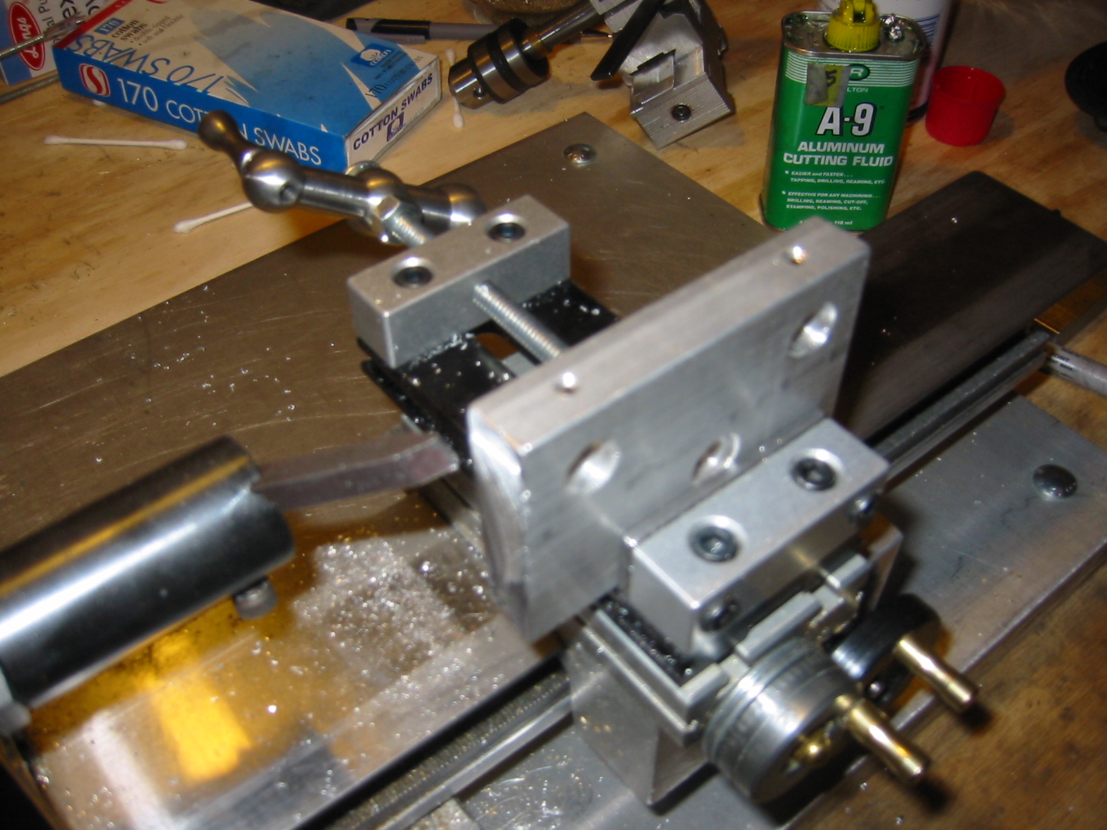
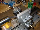
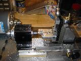
The shuttle for the Y-axis is cut from a piece of
aluminium bar stock. Rather then file the edges square I
tried something new using the horizontal milling
attachment for my lathe and fly cutting the surface
square. It worked but only just. In the future I think I
will file pieces to as close to the size I need as I can
before fly cutting or milling them smooth and square.
|
|
|
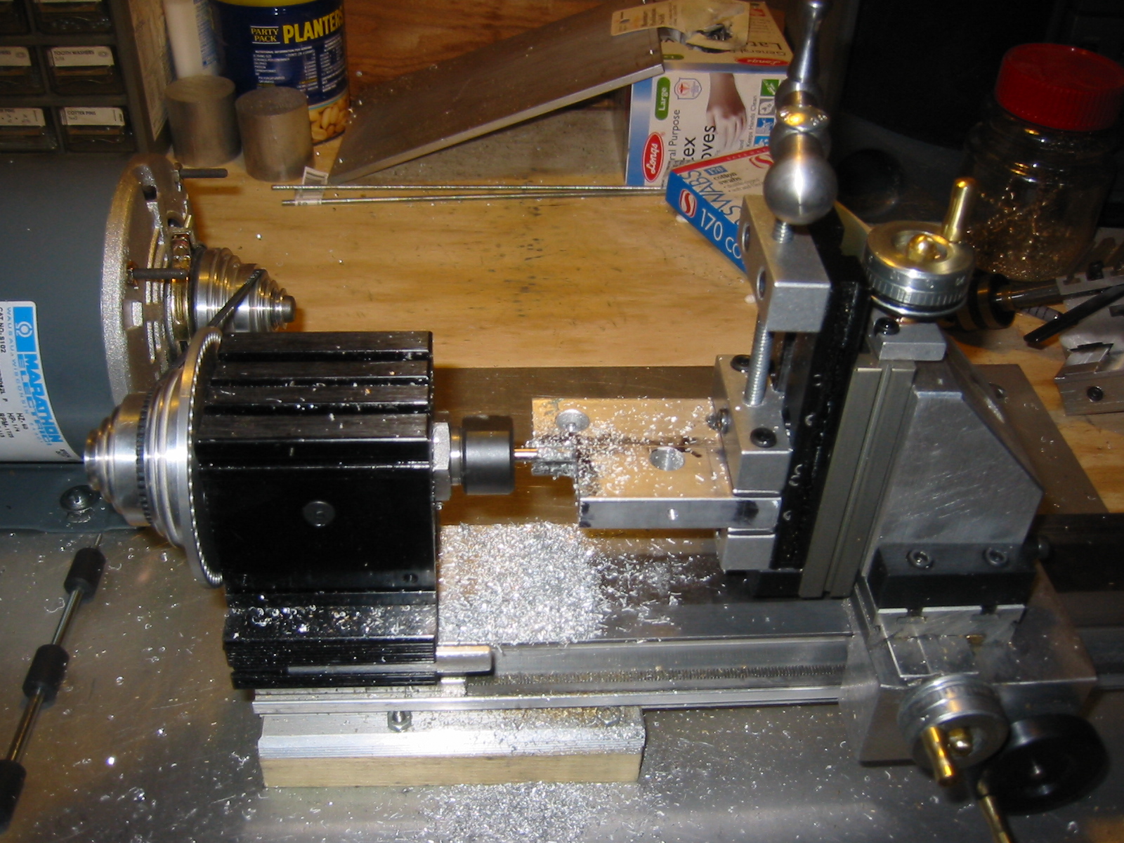
In order to mount the Z-axis to the Y-axis shuttle I needed
to machine the shuttle. Since I have a horologist's lathe I
had to cut the bulk of the material by hand. I hack sawed
out the sections in question, filed them close to true, and
then milled them to just where I wanted them. Time
consuming but it worked fairly well.
|

|

|
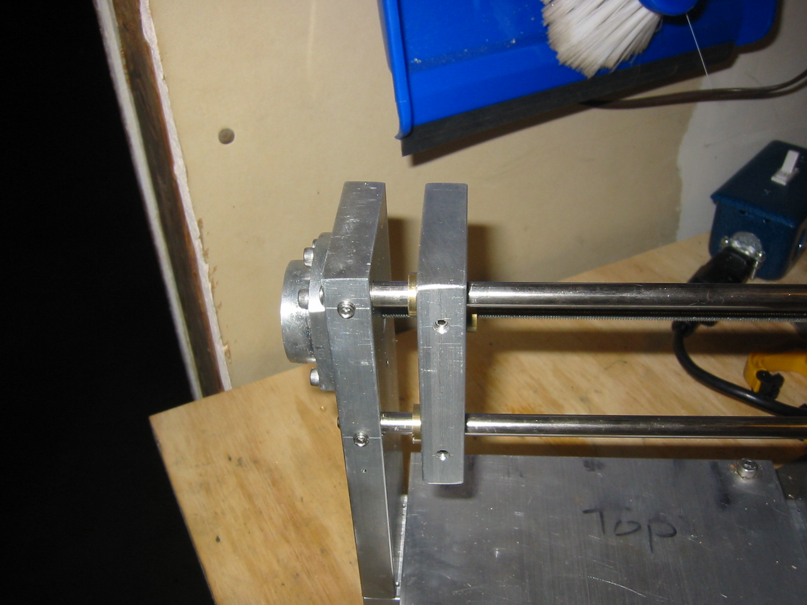
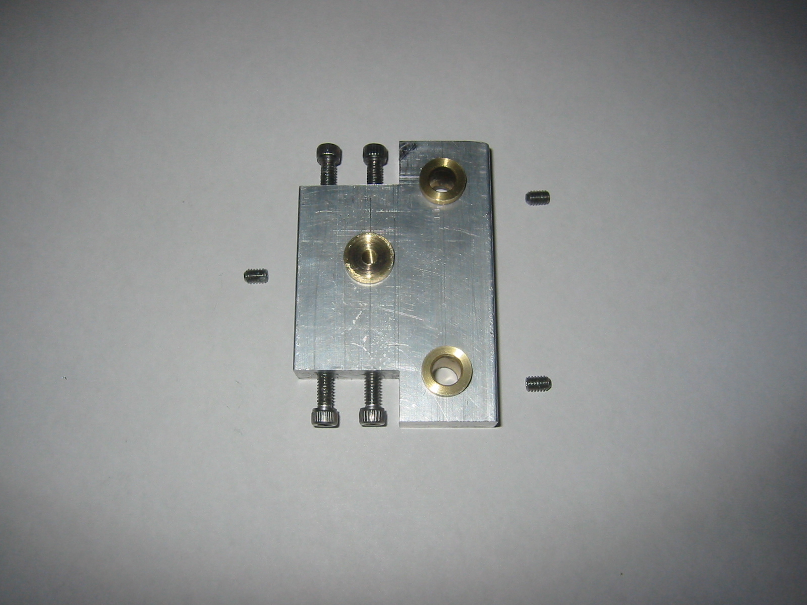
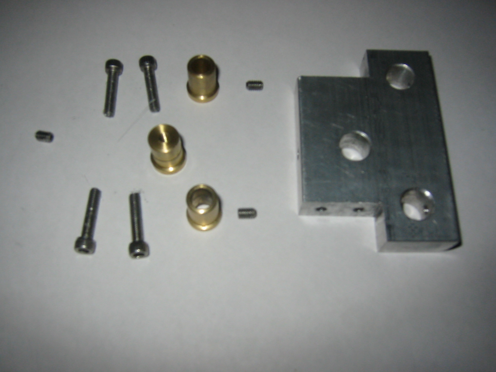
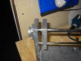
Pictured left is the modified Y-axis shuttle, brass
bearings, and driving nut. I need to come up with a better
design in the future this one was a little over
engineered; too many parts.
|