So with 3D printing finally gaining main stream awareness I get a lot of requests to explain exactly what it is. People generally quickly get the slicking up a model into layers and building up the model a layer at a time. What tends to be harder to visualize is the use of support.
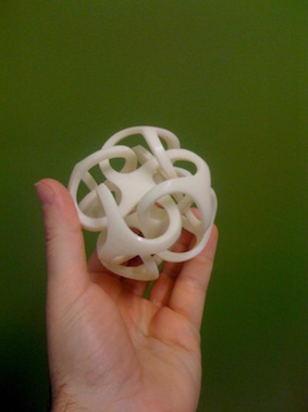
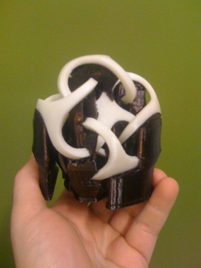
Support is used to support the print material during printing. It is then removed after printing is completed, enabling impossible looking parts to be printed. I think the best example is the artwork of Bathsheba (http://www.bathsheba.com).
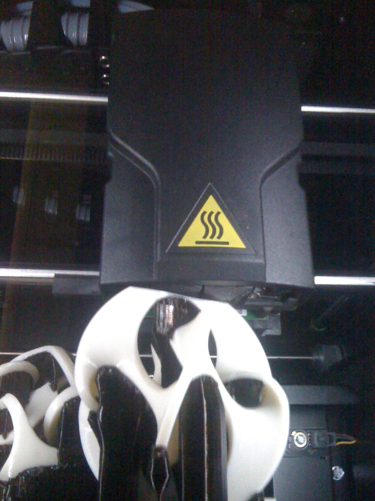
What you see here are two pictures of the Metatron model, both with and without support. The support is the black material and it is dissolved away in a solvent tank. The white material the model is made from is just ABS plastic.
Some printers are built the model from a powder which is blown away once the model is done being printed – but most of the fused deposition modeling use this style of support.
So I realized that I have exactly *one* copy of the circuit I am using for the Gecko drivers. Normally I live out of my engineering notebooks but in this case they were unavailable when I put this circuit together. I am posting the circuit here as I want a backup and I am about to overhaul the electronics for my mill to add a bunch of additional safety features.
It seems I spend more time on this project waiting for glue to dry than on anything else.
Here you can see the tool well before I add the holders for the different pliers and wire cutters.
Need to permanently add the pliers tool well
Despite a frustrating number of measurements and test fits I somehow still had the tools protruding higher than I would like. To drop all the tool heights by another 1/8 th of an inch I ended up cutting a hole through the support base and then gluing in side supports. Grrr.
And this is what going too heavy on the glue looks like
I guess I went heavy on the glue here. Once it dries I am scraping the excess and adding more support pieces – so this first round of gluing was fairly fast and dirty.
So the test fit is a big load off. Everything seems to fit exactly as expected. Not looking forward to making all the little dividers and boxes for the left side of the tool chest.
Right side test fit
Contents of the box as things stand now only have 22 things. I decided to not pack so much into the toolbox. It contains fewer tools but I can carry it farther. Rightnow the box contains:
1. Folding wood ruler
2. Zippo lighter
3. Razor knife
4. Back saw – crosscut
5. 12oz hammer
6. Impact hammer
7. Small lineman’s dike
8. Wire cutters
9. Needle nose pliers
10. Locking pliers
11. Two 1 inch chisels
12. 1/4 inch chisel
13. 6 inch pry bar
14. Try square
15. Speed square
16. Adjustable square
17. Coping saw
18. Hack saw
19. Panel saw – rip
20. Panel saw – crosscut
21. Metal tape measurer
22. Wrecking bar
There are a whole pile of other tools I still need to make holders for – but that is what is in the box so far. Now that I have the tool wells glued up I can check clearance and make the mounts for the lid mounted level.
So one of the projects that has gotten starved for time lately is working on my grandfathers tool box. My father was, among other things, a carpenter. He worked pretty much right up until he went into the hospital and unfortunately the tools he had at his last job site were “lost”. So when my father recently gave me all of my grandfathers tools that he had it was an interesting collection. The centerpiece of which was two of my grandfathers old toolboxes – including his large carpenters tool box.
Largely empty of tools – the toolbox still had the original wooden dividers my grandfather had made and was filled with an odd assortment of tools (e.g. braces, bits, a crow bar). Now that my dad is retired he also gave me some of his tools and I decided to make new dividers combined with the tools I had gotten from my father re-stock the toolbox.
After taking the dividers in and out of the tool box a dozen times to confirm fit after each modification I decided to make a scale cardboard version of the sides of the toolbox so I could work on the toolbox like one of the sides was removed. Below you can see the tools lid out for test fitting.
Cardboard prototype to test layout
In case you are wondering why it is so much work to just stuff a tool box – maybe it would help to understand the requirements. The toolbox is 32 inches by 9 inches and eleven inches tall at its peak. The top is angled so it is not quite as large as that would make it sound. My goal is to be able to pick the toolbox up and comfortably carry it with one hand. So I am putting an absolute limit of 50lbs on its weight when full of tools. I would also like to be able to get at commonly used items without having to move another tool, or at worst having only to move one other tool.
Here is what I have in the toolbox so far…
2 pannel saws – one cross cut and one rip
Backsaw – dovetail saw filed crosscut
A hacksaw
A coping saw
A pad saw
Crowbar
Cats paw (small pyrbar)
Tiny cats paw
Try square
Speed square
Adjustable square
Framing square (leg of which sticks up out of box)
Large razor blade knife (with extra blades)
Several small razorblade pen knives (with extra blades)
Marking knife (for dovetails)
Carpenters pencils
Folding carpenters ruler
Tape measure
12 inch steel – cork backed ruler
Zippo lighter
Pencils
Notepad
Calculator
Plum-bob
Needle files
Level
Wallet for extra plane blades and extra blades for the different planes
2 1” chisels and 1 1/4 inch “beater” chisel
Angled marking gauge
Combination spoke-shave (round and flat)
Sharpening honing stone
Small bottle of honing oil
Hand scrapers in leather envelope
Small bull nose plane
That sounds like a lot but the crowbar and cats paws go in the small saw till at the back of the box, and the right front half of the box forms an open tool well that got filled with specialty holders. So things can get packed fairly tight and yet be easy to get out without tools banging together.
I still need to finish holders but I know where the following tools will go in the box
Diamond needle files
Collection of dentil picks
Assortment of small sandpaper squares
Telescoping mirror
Telescoping magnet
String level
Plastic impact mallet (for chisels, and “persuading” things)
Hammer
Low angle Jack plane
Skew block plane
Small Rabbet plane
Screwdriver for plane adjustment
Tiny brass hammer for blade adjustment
A Stanley 60 1/2adjustable mouth block plane
Needle nose pliers
Lineman’s “dikes”
Small wire cutters
Locking pliers
Chalk snap-line
Even with all that there is still some room to work with. My problem is that I still need to pack in the rest of these tools / items.
Torpedo level
Small hand mirror
Several neodymium magnets
Several 1 and 3 inch C clamps
String for line level and plumb bob.
Several bevel edge socket chisels for dovetails
Extra blades for coping saw and hack saw
Glass cutter
Push drill and bits
Set of good screwdrivers
Earplugs
Eye protection
Rag
Leather work gloves
Small thing of super glue
Needles and thread
Simple first aid – band aids, antiseptic cream, ibuprofen packet
My main problem, I think, will be figuring out how to get the screwdrivers in the right side tool well – and easily accessible – without making it hard to access they other tools.
Below you can see me laying out my planes. They will sit in a small wooden pull out drawer. The pulls out portions are going to be made from cherry – while inside the box I am using mostly poplar and a decent grade of plywood.
Planning layout for plane pullout box
The planes above are a Lie-Nielsen sckew block plane, low angled jack plane, and rabbet plane. The jack is amazing in that it can be set for rough or finishing work. I have a spare blade for it and also got a 90 degree scraper blade to be able to use it for finishing. The skew block plane is useful for both a block plane or for use in dadoes. I have a set of side rabbet planes and a place reserved for them – but I am still on the fence about adding them.
Left side storage area
Here you can see the left side of the box. There is a small well area on the bottom of the box. That is where the oil-stone and plumb bob will live. This is where I am thinking the chalk snap line will go. Along the side of the space is a pocket for the scrapers and a bin for pencils and pens. The reason there is about a quarter inch of dead space along the side of the toolbox is that is where one leg of the large framing square sits when in the box. It is a bit of a hack but I plan on sewing an envelope to hold an assortment of pieces of sand paper. That envelope will sit on top of the carpenters square in this dead space.
The drawer with the plane box sits atop the left side storage well. I should also be able to have another box atop that and then room for a smaller pull out tool drawer at the top of the box. The layout was bugging me so I went and made a cardboard mockup of that top drawer. That way I can build it and the plane drawer and then make the center box to fit. Not quite optimal but I am fairly sure I will be able to fit the chisels I want – as well as the sewing kid and some other tools in those center boxes.
Cardboard prototype of left side top lift out tool drawer
Here is what the right side tool well looks like – if the back of the toolbox were removed. This has proved the most useful attribute of the cardboard mockups of the box’s sides – being able to visualize the insides as if I had x-ray vision. It is kind of like making simple test cases when developing software.
Right side tool well and storage area
So I am currently laying out a small set of holders to go next to the chisels, but on the other side of the coping saw. Should look something like the picture below. I am still trying to figure out if I want to have dividers between the tools. On the one hand it would keep the tools from rattling around but it would mean I would have to have *those* tools and could not swap tools in and out as needed. Still on the fence about how to do this.
Planning layout for new tool well in right side tool well
I was having a crappy day yesterday and the best prescription for that is always to check something off of my to-do list. My leg vise had been sitting half finished on the corner of my workbench bugging me so it seemed the job. I drilled the vise jaws and attached the screw from a cheap grizzly workbench.
My new leg vise!
I was looking forward to having the vise but it is a huge improvement over the other vise on my bench. Kind of odd since it is the same screw mechanism. I might have mounted the screw a little too low but I am very happy with it. I really should take some time and clean up the look of the leg. As this was my first leg vise I was just shooting for functional – but since I get the feeling I will be using it a lot I should probably go back and clean up how it looks.
Helping my friend Joel move I noticed this wire rack in the corner. He said he just threw it together to hold all the different spools of wire he was using on a car rebuild he was doing. I really liked the design. I use a hanging rod to hold my wire at the moment but think I will replace it with a rod held by a wooden rack like this.
Since I cant afford the time or money to make or buy a cabinetmakers workbench I decided to improve the Grizzly bench (H7724) I already had. I already added a plane stop – so the next thing to add is a leg vice.I already had two of these benches in the garage – so I am steeling the vice hardware off of one of the benches to make the leg vice.
The first thing I did was to attach a 2×10 to the leg of the workbench. This will act as the base for me to build out one leg of the bench so it is big enough for a leg vise. I used the plane stop to plane down stock from the lumberyard so it was flat and without twist. Then I roughed up the leg of the workbench and glued the board to the leg. I used woodscrews to help secure the board to the leg.
Once the glue had dried I came back and glued another flattened 2×10 to the first. The combination should give me a solid foundation for the leg vise. I also made sure to plane down the second board so that it was flush to the edge of the table
Grizzly sells a really nice bench with lots of drawer space. I already had two of these benches in the garage – and rather than buy or build a cabinetmakers workbench I decided to improve the bench I had and use it until my woodworking projects outgrew it.
The first thing I wanted was a plane stop. The stop is basically a board that sticks up proud of the table surface by an adjustable amount. Here you can see a profile of the stop.
The stop attaches to the end of the bench by two bolts. I milled slots in the stop board to allow it to slide up and down. The board is held in place by friction and adjusted by a quick light taps with a hammer. I have some ideas for a screw lock for the stop – but so figured I would use the friction adjustment first and it seems to work great.
Below you can see the stop in use. A board rest against the stop so the length of the board can be planed right out over the edge of the board. This is useful for thicknessing stock by hand.


