So what is this all for? As part of my PhD research I needed to target some sensors. Edmond Scientific and others sell tageting bases for anywhere from $200-$1500 USD. Since I am going to want a lot of these and I needed a better option. What follows is a description of the cheapes, simplest, mount I could come up with. If you build this design or a variant of it please let me know and send me a picture to post here. Especially if you come up with a cool cheap hack to tweak performance.
Eventually I want to be moving around a few CCD cameras, sensors, and mounting hardware. CCD cameras are light and most people just mount them directly to two servo motors. (Here are two such example designs in plastic and metal). The problem with this approach is that the plastic gears inside the servo takes the entire load and hence as a solution it does not scale.
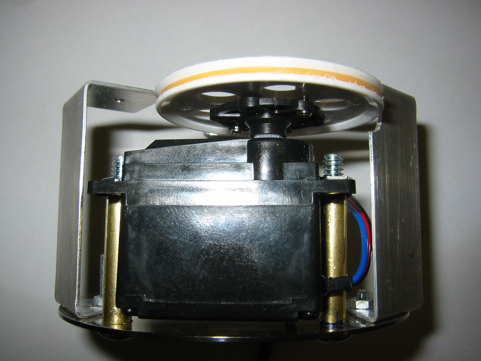
To keep all that weight from bearing down directly on the servo's plastic gears I used a pulley system to isolate the load from the servo. This type of design places almost no load on the servo and can be heavily loaded. Unfortunately though the cost of the pulleys is that the load is slightly elastic in response. In future versions I will probably move a gear driven version. The nice part about the pulley (or gear) approach is that by scalling the relative sizes of the pulleys (/gears) you can increase the angle over which the servo rotates. I am using almost a 2:1 ration obtaining over 400 degrees of rotation from the servo.
The whole design was put together for about $43, $25 of that being the cost of the servo. Everything here but the servo can either be picked up from any hardware store or scavenged from the hardware scrap pile you almost assuredly have somewhere in your house.
From the hardware store obtain some 2.5cm wide aluminum strip and a box of small machine bolts and nuts. Just get the smallest ones they have. I used metric M3x15 threaded screws and matching hex nuts. You also want to buy at least two larger bolts for mounting the servo. Buy the servo motor before going to the hardware store and measure the size of the mounting holes on the servo. Then just buy the appropriately sized bolts. Total cost leaving the hardware store is about $11. If you can't scavenge the pulleys from any junk you have about the house a set of 6-8 usually runs about $7 dollars at the hobby shop.
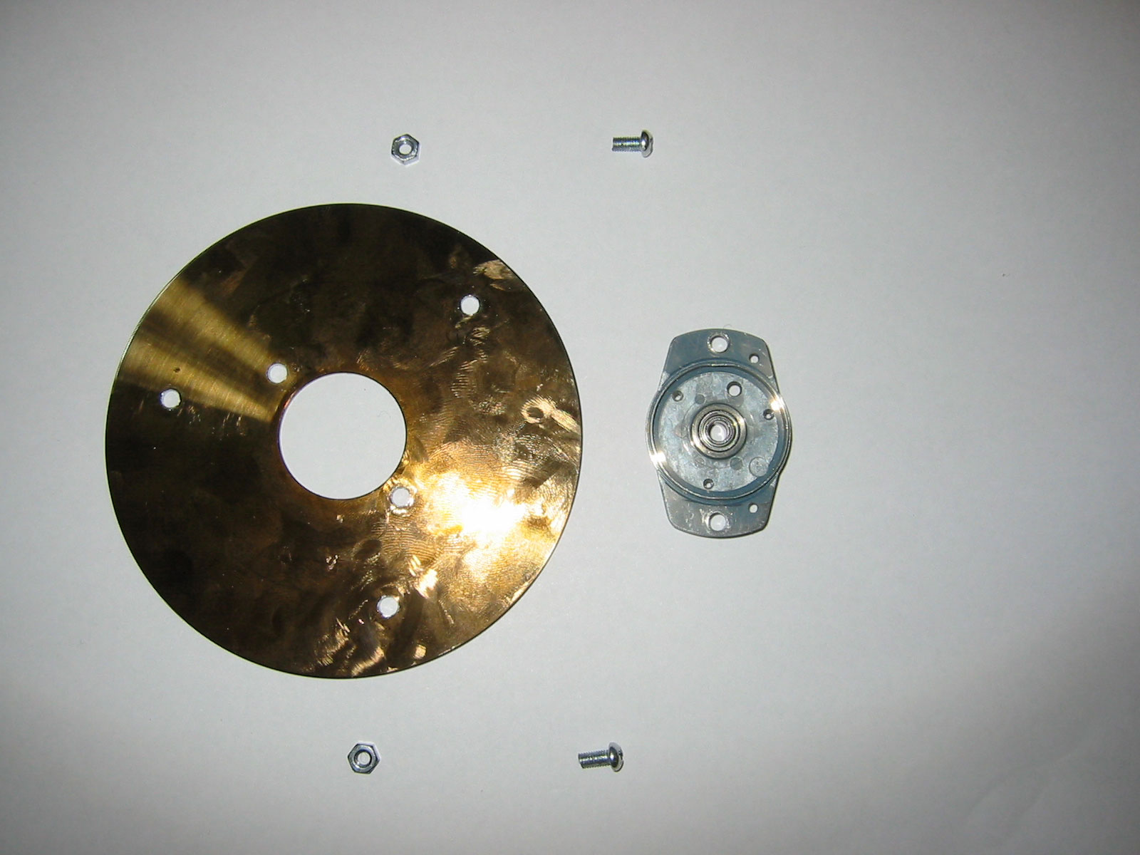
First dig though some old 3.5 inch floppy drives looking for bearings. The older the drive the better. The newer drives use press in bearings. They are still useful but not require a lot more messing about to get out and reuse. In a fairly old generation of 3.5 inch drive you should be able to obtained a screw mounted bearing like the one shown below.
|
|
|
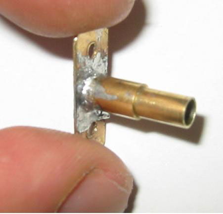
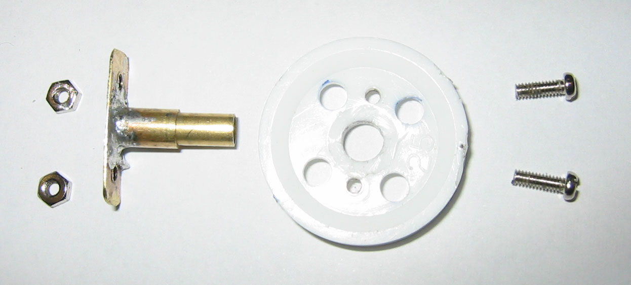
The most time consuming part of the design in making a T shaped bearing sleeve. This sleeve should be made from brass and allow for a bolt or screw to pass through its center and that of the bearing. Solder works well for securing the brass pieces together. The bolt/screw will be what fastens the top plate to the pulley. Two smaller screw are used to mount the T to the pulley. The sleeve length sets the distance that the pulley sits above/below the bearing. | |||
|---|---|---|---|---|---|
|
|
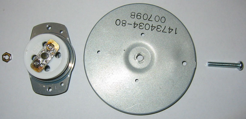
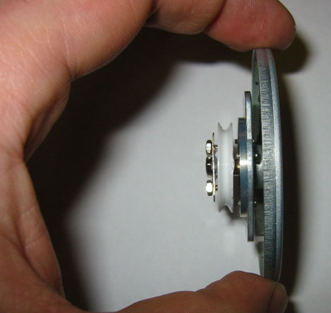
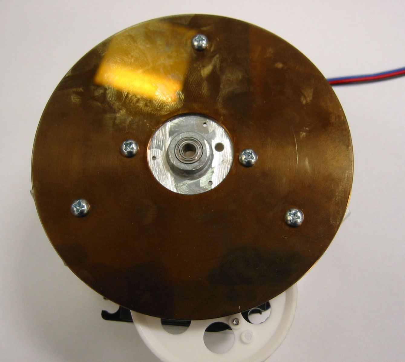
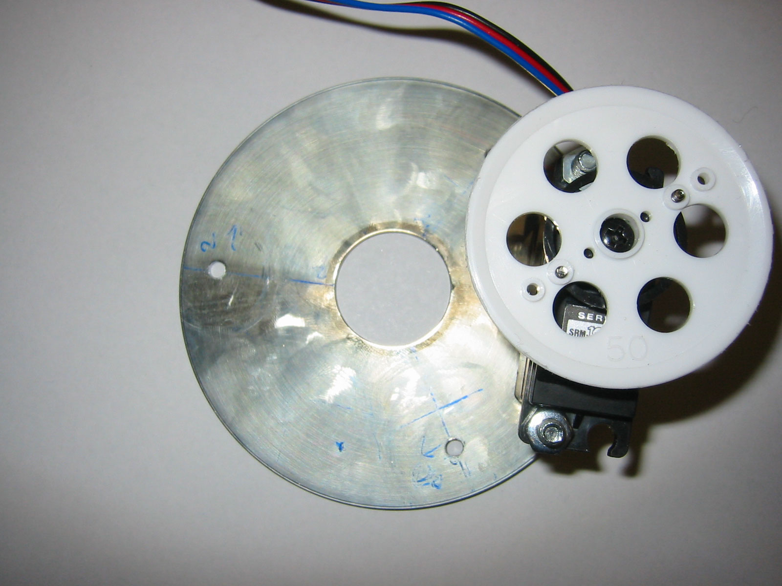
Remounting the bearing to the original plate from the floppy drive we can see the pulley / bearing module. This in itself could be used to give a cheap rotate-able mounting platform. | |||
|---|---|---|---|---|---|
|
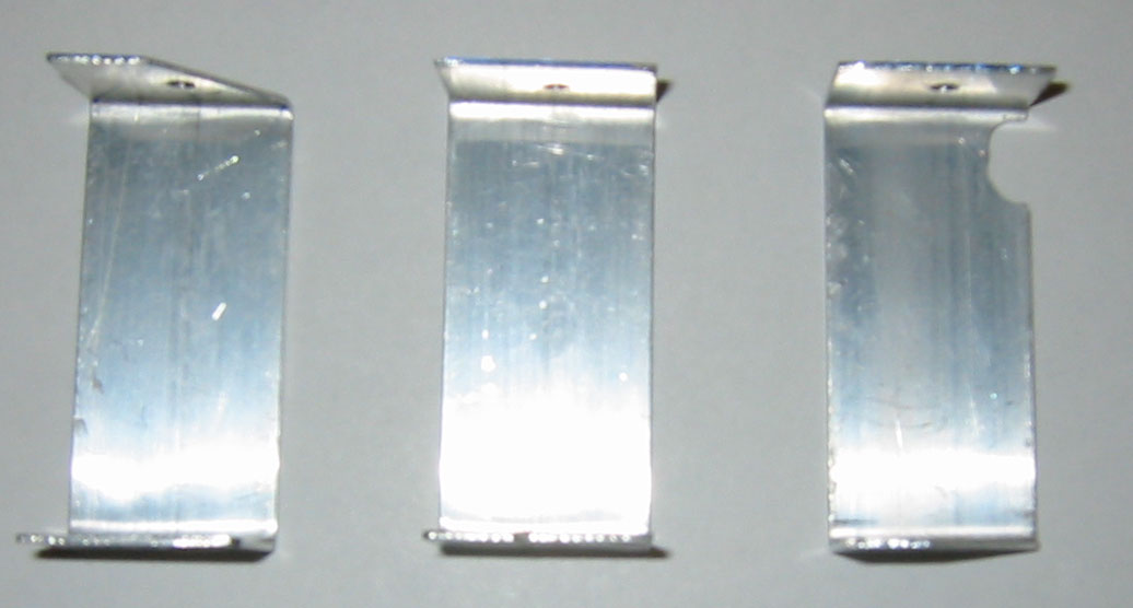
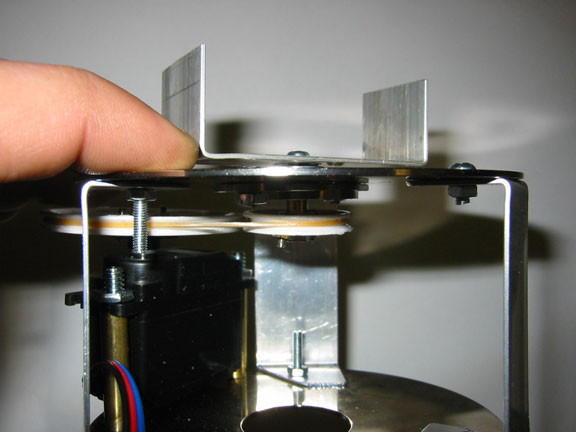
Three 1 inch strips of aluminum have been bent to form u-shaped standoffs. I spaced the standoffs 120 degrees apart from each other. I would strongly recommend that after you mark and drill the holes in the base and standoffs you label each hole/standoff pair. This is after all a scratch build and accounting for variations in alignment will save a lot of time later on when modifying the base. Due to the use of a large servo pulley I had to cut a small groove in one of the standoffs. (as shown) |
||
|---|---|---|---|
|
|
The top and bottom of the base are made from scavenged hard drive platters. The one thing to be leery of here is to make sure you get the platters from a vintage hard drive. Newer multi - gigabyte drives switched over to ceramic platters. Make sure you test the platters before you try and drill them so they don't shatter. | |||
|---|---|---|---|---|---|
|
|
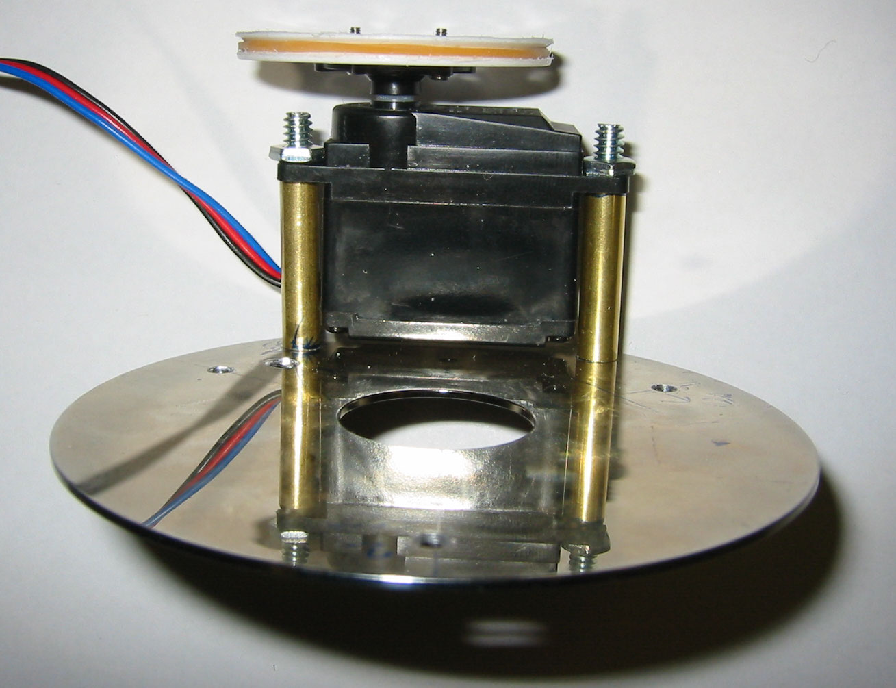
Once you have drilled and mounted the bearing sleeve and the standoffs take everything apart. At this point you want to mark and drill the holes for your servo mounts. The mounts themselves are actually pretty simple. Two mushroom headed screws with nuts used to cap down the servo on one end. The servo is then stood off of the bottom plate with brass sleeves. The brass sleeves can be measured then filed until they have the desired height. |
|||
|---|---|---|---|---|---|
|
|||
|---|---|---|---|
|
|
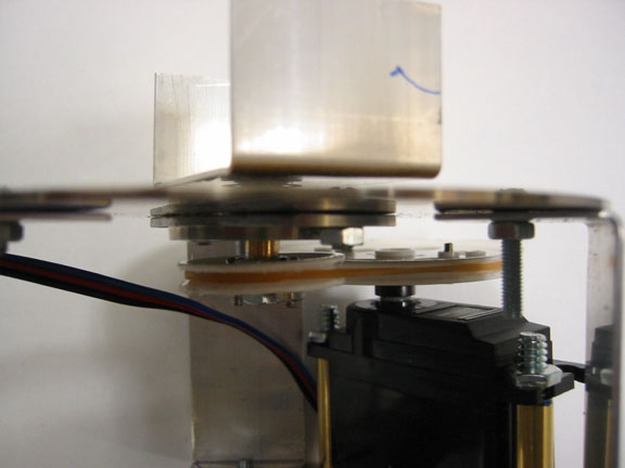
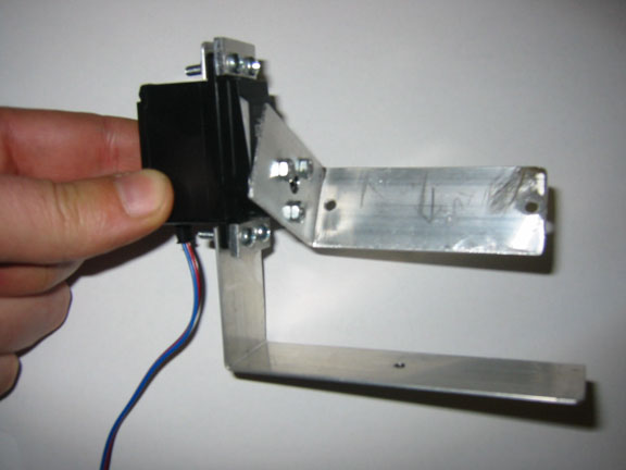
Left you can see the finished pulley setup. The U-shaped metal mount at the top of the base is just a place holder for the design. Ultimately that would be replaced with a mount like the example camera mount shown below. |
|||
|---|---|---|---|---|---|
|
|
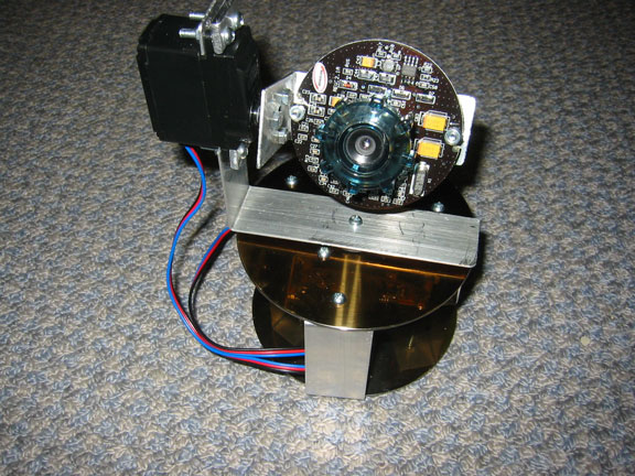
This servo/camera mount was just something I threw together to get a camera targeter to play with from the base. It doesn't really take advantage of all the weight this base can support. |
|||
|---|---|---|---|---|---|