My Thrust Bearing Design


Ok, if you are a machinist turn back now. This was one of my first self imposed projects. I am trying to learn how to machine material in order to increase my prototyping ability.

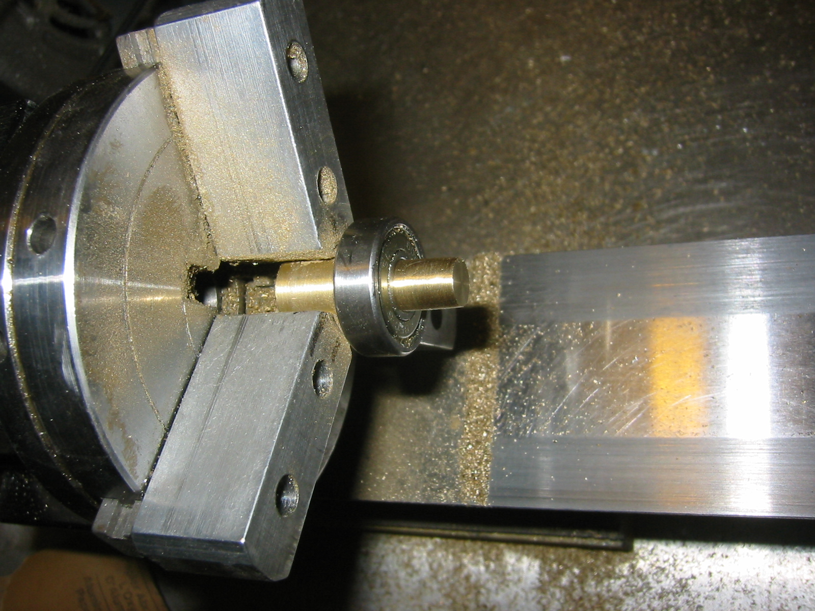
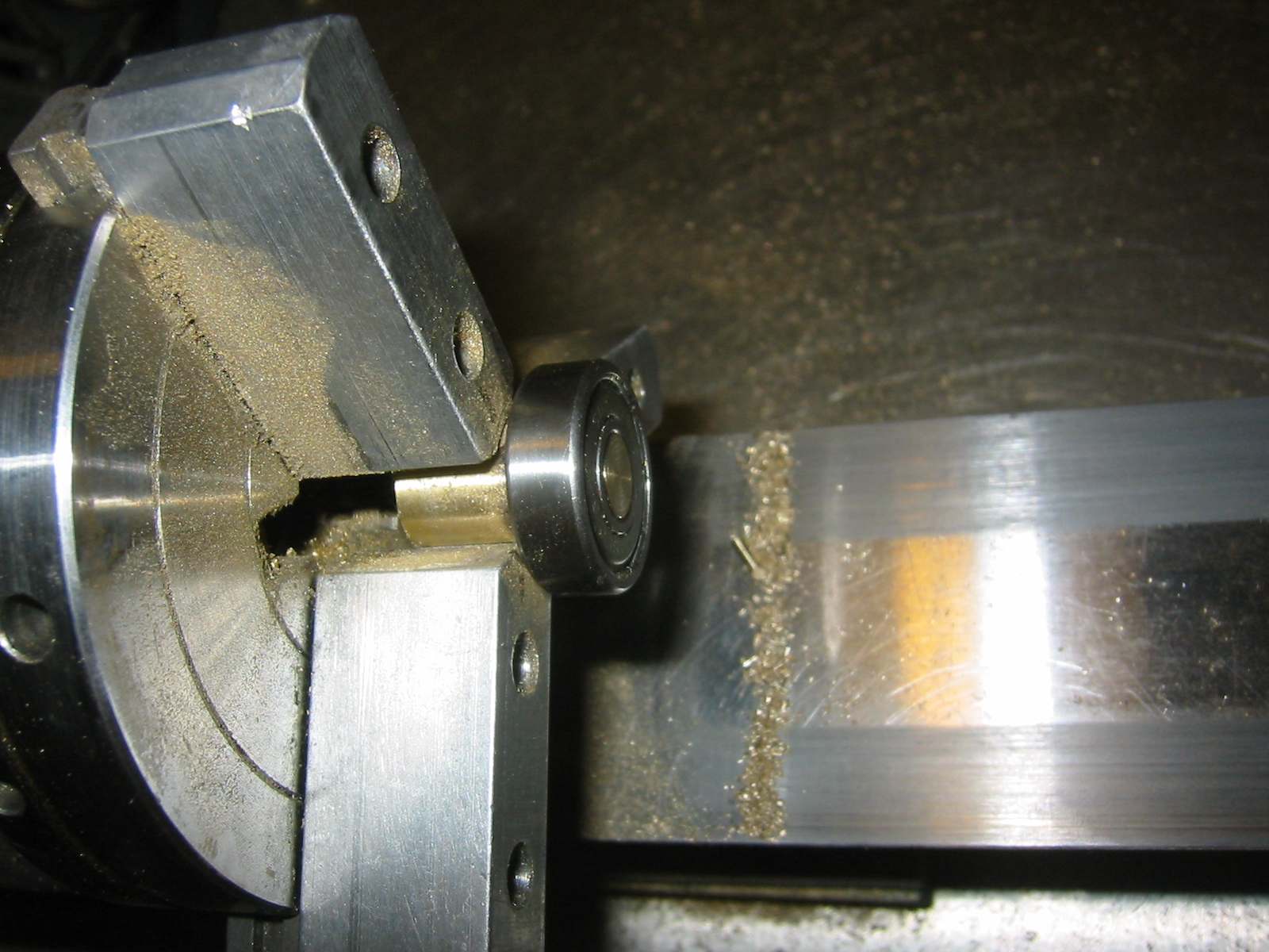
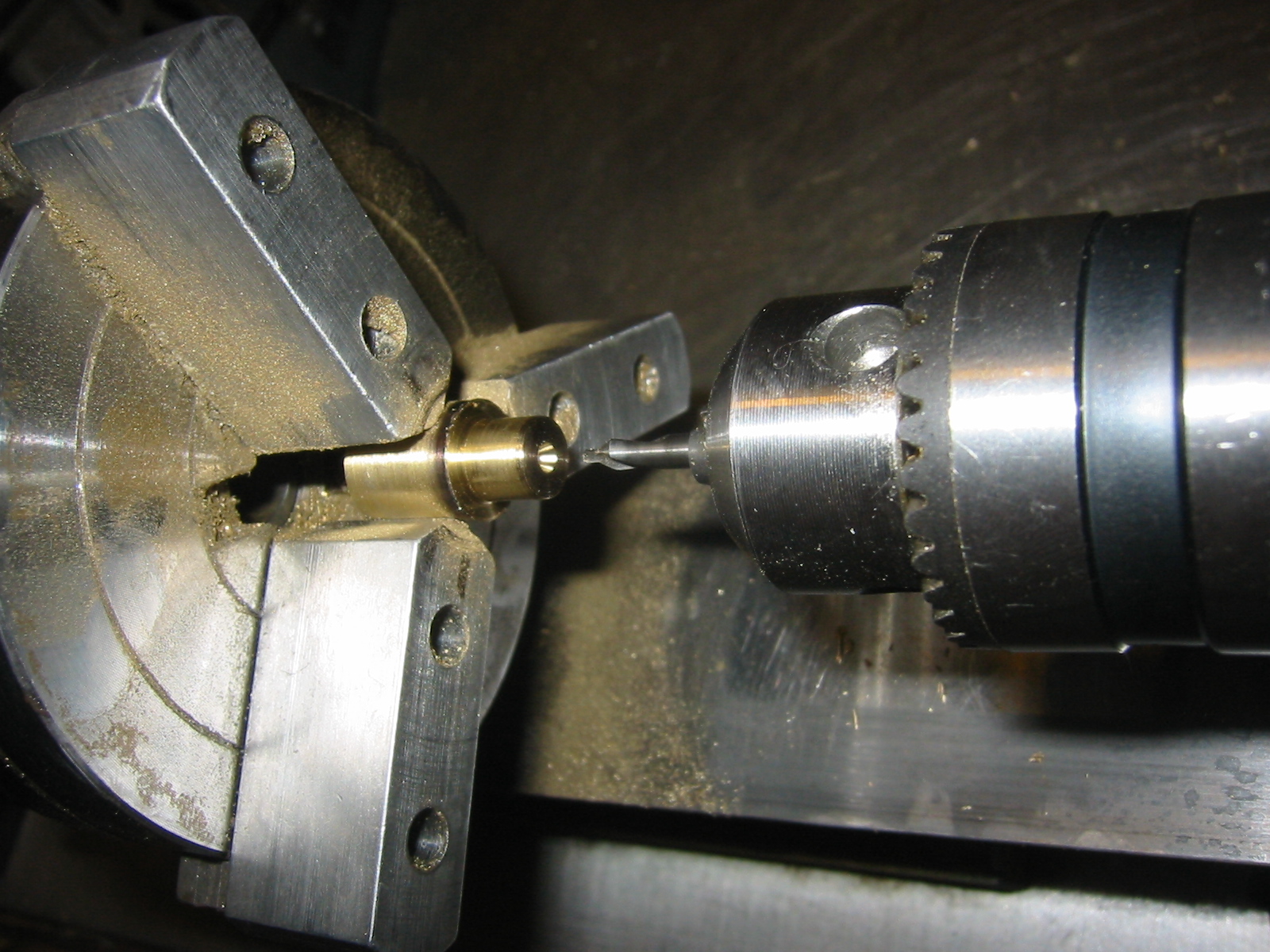
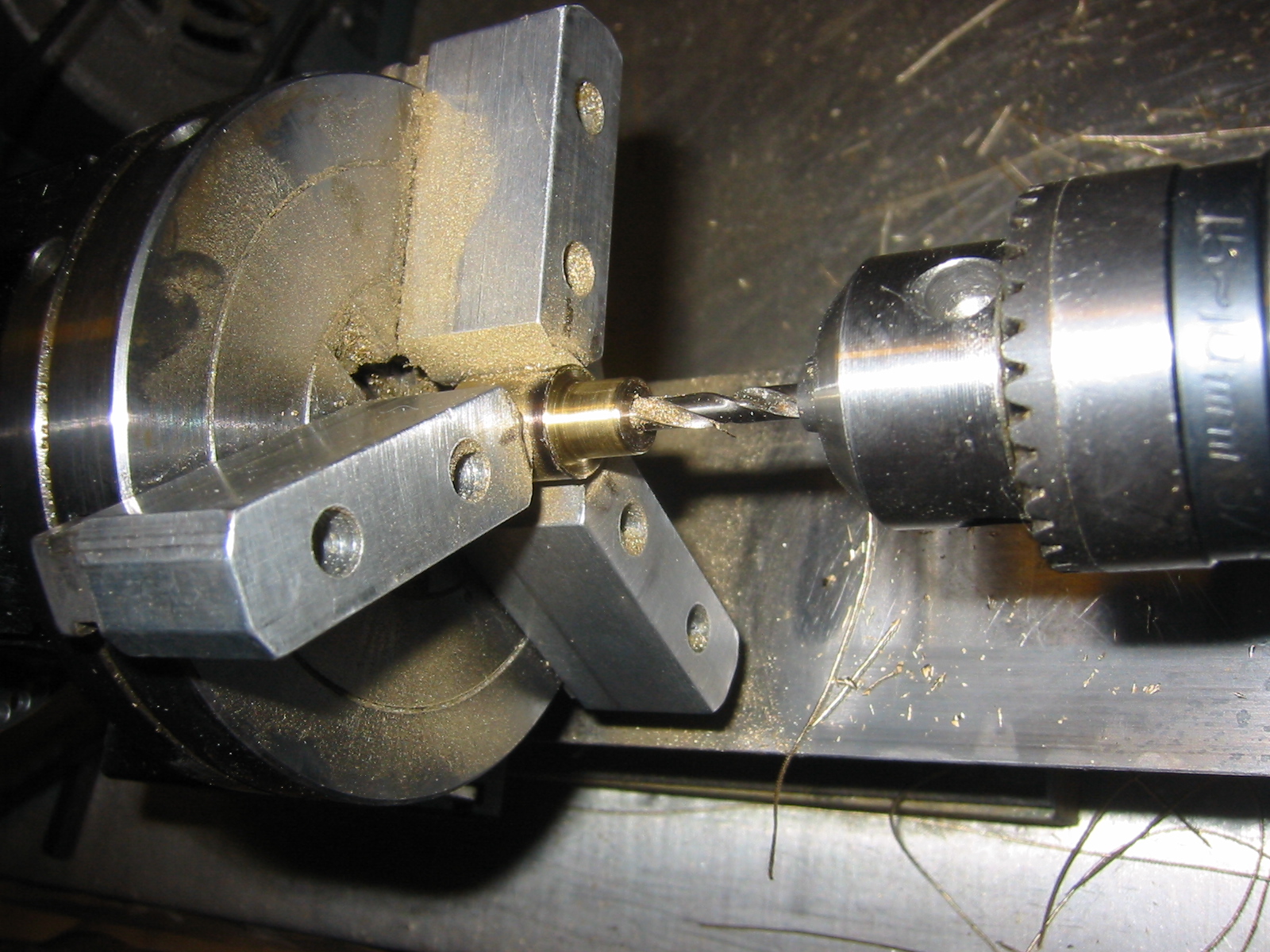
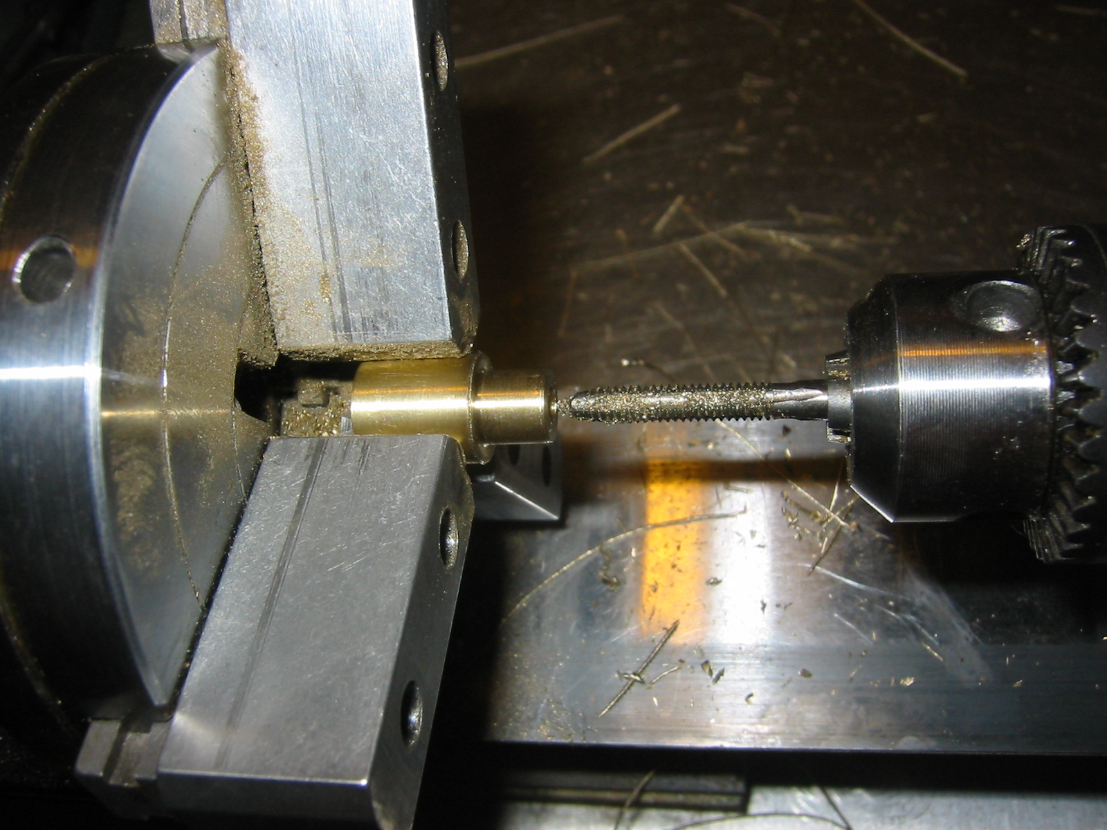
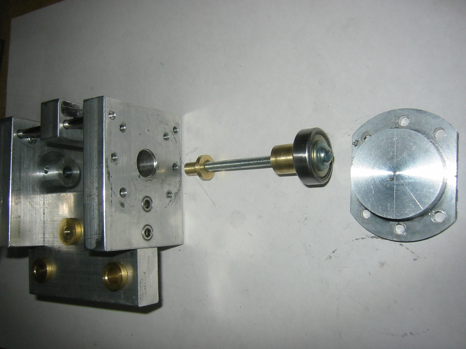
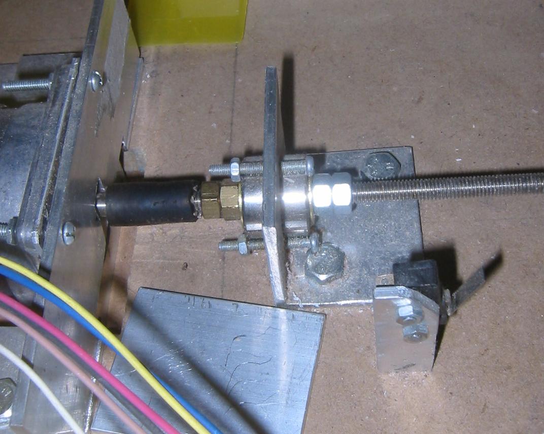
In order to build a small CNC milling machine I needed to build three thrust bearings, one for each axis. There is a common thrust bearing based on a roller skate used in the hobby CNC community. This design is my version of that design. In the first CNC mill I worked on with Ross we used that design on the X axis. You can see that thrust bearing shown left. Basically the bearing has a stem that is captured at one end the inner racing of a bearing. The outer part of the bearing is held in place. As a result the stem will not move laterally but is free to rotate. A thrust bearing like this is usually attached on the end of a threaded drive rod opposite the motor.

Casting the Bearing Cover

While the Taig lathe is a serious little work horse it would have been quite a task turning down the three bearing caps I wanted from solid bar stock. In the end I ended up knocking up a wooden template of the bearing cap and then casting it out of Aluminium. If you are interested in the casting process I describe my various aluminium foundries here. The patterns were cast using green sand. The piece is shown cooling left and with the cope and drag parted to the left.

I still have a lot to learn about casting. After having a lot of problems with sprue placement I finally found that for smallish pieces it is best to ram the sand with the sprue to one side of the piece and then carve away the sand between the sprue and the pattern piece. Not sure if it is good practice but it seems to work well and reliably.

Machineing the bearing cap

I am still learning how to reliably get the sand not to stick to the pattern. I think the moisture of my sand is slightly off. Once I get out of grad school I am planning on building a small Muller to churn the sand before casting. I think that should help. Still you can see that the piece comes out fairly close to the original.

After cleaning the sides slightly with a file I chucked up the piece in a four jaw chuck. From there I faced and then rounded the outer part of the cap.

You can see that the cast aluminium bearing covers machine up fairly quickly. Once the cap has been cleaned and rounded I flip it around in the chuck and hollow out the cavity which holds the roller skate bearing.

First I marked the center of the cavity which would house the bearing. From there I center drilled the piece. The next step was to turn a slight recess the intended size of the cavity. This lets you hog out a lot of material until you get close to the cavity dimension. From there you can be more precise in your cuts. To hog out the material I used the largest drill I had and drilled into the cap and then used the lathe and a boring bar to increase the size of the hole to the desired size.

Machining the bearing stem

This bearing design uses a captured stem. The stem is attached to the inner part of a roller skate bearing. The thrust bearing spins freely on its axis while taking force along the axis of rotation.

Ok, so any machinists looking at this are going to be groaning but I cheated. I test fit the bearing stem inside the piece I was making. While I got a really good fit I really should have been able to do it just with callipers.

Ok, I used the same cheat to ensure that the bearing stem fit the roller skate bearing.

Once I got the stem to fit I trimmed it down flush with the bearing. This was, of course, not done with the bearing on the stem. The picture just shows me test fitting the piece.

The stem was then center drilled, drilled, and tapped.

The stem was not drilled all the way through. It is actually drilled and tapped partially from either end. On the cap side a screw holds a washer to capture the bearing. The cap prevents the stem from moving in one direction and the washer prevents the bearing from being pulled in the opposite direction.

Example Bearings

The example picture on the left shows how the washer captures the bearing stem.


Email -- joeboy @ hhhh.org
Back to my home page.