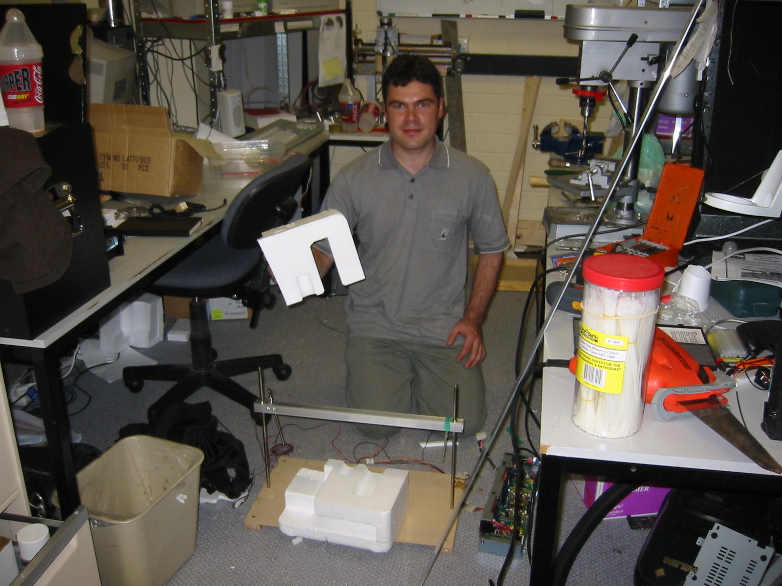
Building a Hot Wire Foam Cutter
|
Hot wire foam cutters work by heating special wire to the
point where it vaporize foam it is brought in contact with. It is a
technique commonly used commercially and hot wire foam cutters are
available for any where to several hundred to several thousand
dollars. Heck, I will happily sell you mine for a fraction of that but
you should probably know that it only cost me $4 to buy the resistance
wire or nichrome plus maybe $15 - 20 dollars in scrap stock I already
had.
I leave it to the reader to supply their own power supply. I
am using a supply from an old external SCSI drive. My cutter runs from
the five volt supply and 25cm of nichrome wire pulls about 900mA or
4.5 watts. That is actually running a little hot and I plan on
building a temperature control circuit shortly. I have read that the
key to successfully hot wire cutting of foam is apparently "slow and
cool". After my initial experiences I believe it.
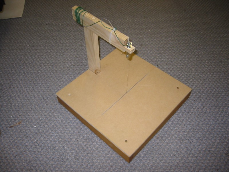
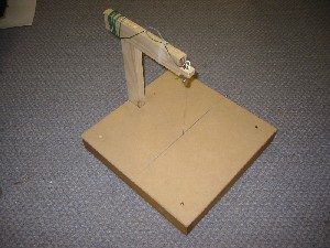
My design is pretty simple and breaks down into four parts;
base, top, shuttle, and cutting arm. Each piece is described
below.
|
Shuttle
Ok, so this feature is not strictly necessary. I added a
shuttle to allow for a variable cut angle on the cutter. When I
researched home build foam cutters that other people h ad built it
seemed to be one of the big features everyone wished they had added to
their design.
|
|
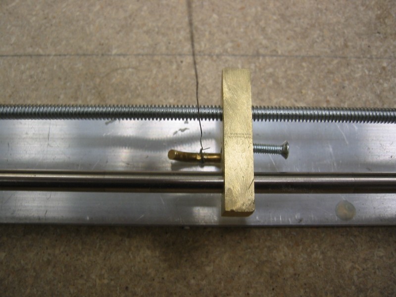
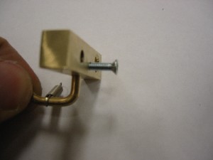
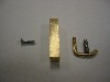
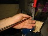
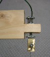
A small hook extending from the base of the shuttle bar holds
one end of the heated wire. The shuttle is driven to a desired
position along a lead screw. Adjusting the position of the shuttle bar
along the screw allows for an adjustable cut angle. Recall from your
Trig that the higher your support arm the father your shuttle will
have to move to reach the desired cut angle. For the default bar on my
cutter for example, which is 20cm high, a maximum cut angle of only 30
degrees can be achieved. That can of course be increase by lowering
the cutting arm. With this design it is simple to have multiple
interchangeable support arms with differing and heights.
|
|
|
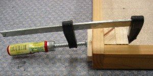
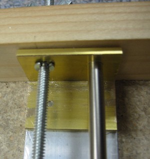
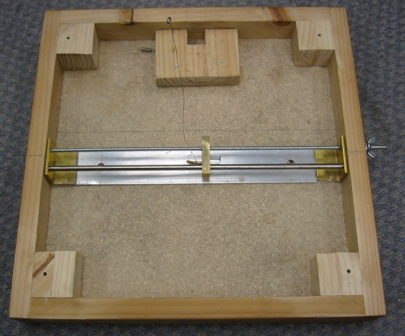
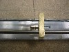
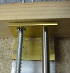
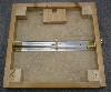
The bar is driven along the lead screw while a piece of steel
rod is used as a guide. The rod keeps the threaded rod from
taking the entire load. Probably overkill for this
application but it is simple to add and ensures the shuttle
keeps working without binding.
I used 1/8 inch 24tpi threaded rod and 3/16 inch steel stock
but only because that was what I had in my scrap box. The
loads here are so light that any straight steel rod will
work for the guide or lead screw. As a suggestion you should
probably look for the lowest TPI on the lead screw you can
find.
|
|
|
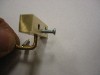
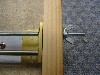
The screw that you see running into the block is used to attach a
ground wire to the shuttle. This ground complements the positive
terminal on the support arm.
|
Base
My base was build around an old wooden monitor stand. Pretty
much any sturdy wooden base should work with this style of design. I
would recommend finding one that will fit your intended power supply
so that your cutter will be self contained.
|
|
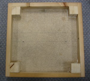
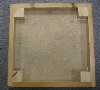
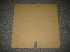
Since I was using a thin top I cut out four blocks and glued
them into the corners of the base. These blocks were then
drilled and formed the seat into which the base's top gets
screwed down.
|
|
|
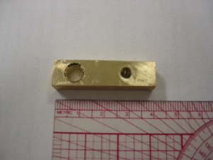
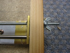
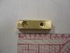
Both the threaded and steel rod are seated in 5cm wide pieces
of brass stock mounted to aluminium bar stock. Both brass
and aluminium stock in this type are commonly available at
most hardware stores. The steel bar is friction fit and
trapped in the base by the walls. The threaded rod on the
other hand needs to extend beyond the case walls.
I used a small piece of brass tube stock as an insert to the
hole in the side of the box through which the lead screw
extends. This keeps the action of the action of the screw
from fraying the wood. The screw is held in place by a small
clip on the inside of the brass support. If you don't have
any cer-clips at hand you can saw cut the file and washer as
I did. I would suggest that the aluminium bar stock should
be screwed into the base as soon as possible in
construction, even if it has to be removed later, in order
to provide a fixed reference to work with.
|
|
|
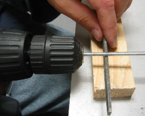
If your are like me and don't have a lathe you can make the
notches needed to clip in the threaded rod with either a
warding or milling file and a triangular file and a hand
drill. Set up the base and mark off where the clip is to fir
the screw with felt tip pen. You will likely have to do this
several times so keep things handy.
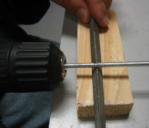
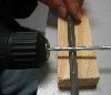
By chucking up the threaded rod you can *slowly* work the rod
along the edge of a file. Make sure you move the rod back
and forth along the file so that wear on the file is
even. If you don't you will ruin the file. Start with the
triangle file to cut the edges to your notch and then remove
the bulk of the material between the notches with a milling,
warding, or similar file.
|
|
|
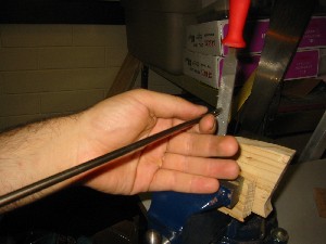
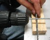
Again if you don't have a lathe you can flatten the ends of
round stock by chucking it in a hand drill and slowly
working it against a file. Use wood blocks to sandwich your
file in a bench vice. Then slowly work the rod across the
file. The averaged out surface will be close to flat and
tangential to the axis of the rod's rotation.
|
|
|
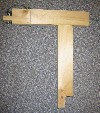
The last piece to add to the base is the "u" shaped support
block that holds the support bar. The support bar on this
design is friction fit. The fit needs to be tight enough to
firmly hold the arm in place yet loose enough that the arm
can be removed for storage or to change arms. Not hard to do
just a lot of filing and measuring to get it right.
|
Base Top
|
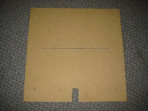
The base is cut to size to match the base. Then four holes are
drilled to match the pilot holes in the corners of the base. Use
counter suck screws and bevel the edge of the holes so that the
face of the screw sits flush with the tabletop.
Since the support arm is friction fit once the screw holes
have been added attach the top and mark arm. Make sure that you
under cut the measured mark slightly and then repeatedly file and
measure the opening to get a tight friction fit.
The slot for the nichrome wire needs to be measured, marked,
and cut after the shuttle is finished. If you don't have a table
saw or router to make this cut you can mark a line then drilled
repeatedly along that line removing the excess material with a
file. It is not ideal but it is what I did here and if you are
careful it will yield reasonable results.
|
Cutting Arm
|
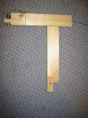
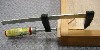
The base of the arm sits on the outside of the box with a toe
extending through the top to be held in place by the "u" shaped
support block. I used a mortise and tenon to quickly join the two
pieces of the arm together. A spring loaded bold mounted on the
arm provides wire tension.
|
|
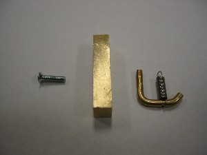
The heated wire is wrapped around a screw on the tensioning
clip. Tightening the screw locks down the wire. The spring loaded
bolt in the arm is screwed into the clip providing tension. A
washer and used below the support arm both to retain the spring
loaded bolt and for use in setting the initial tension level on
the clip.
|
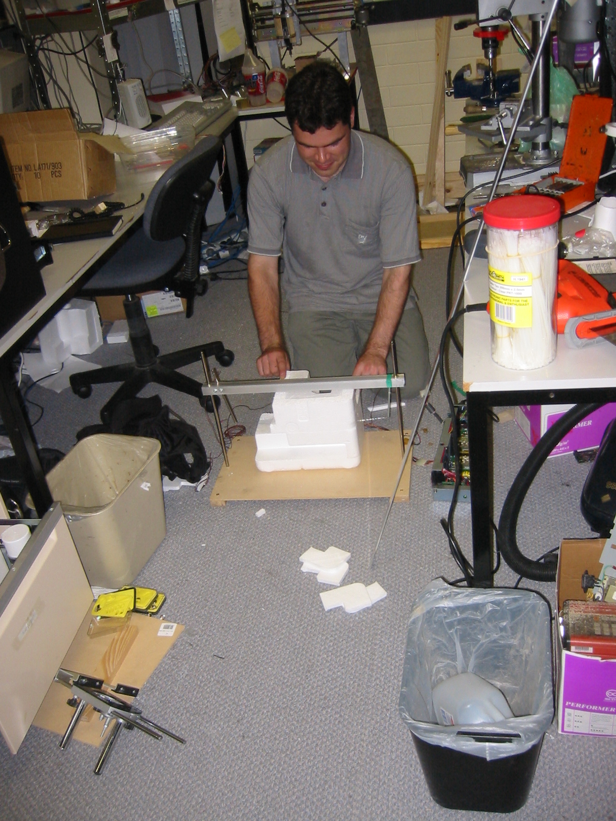
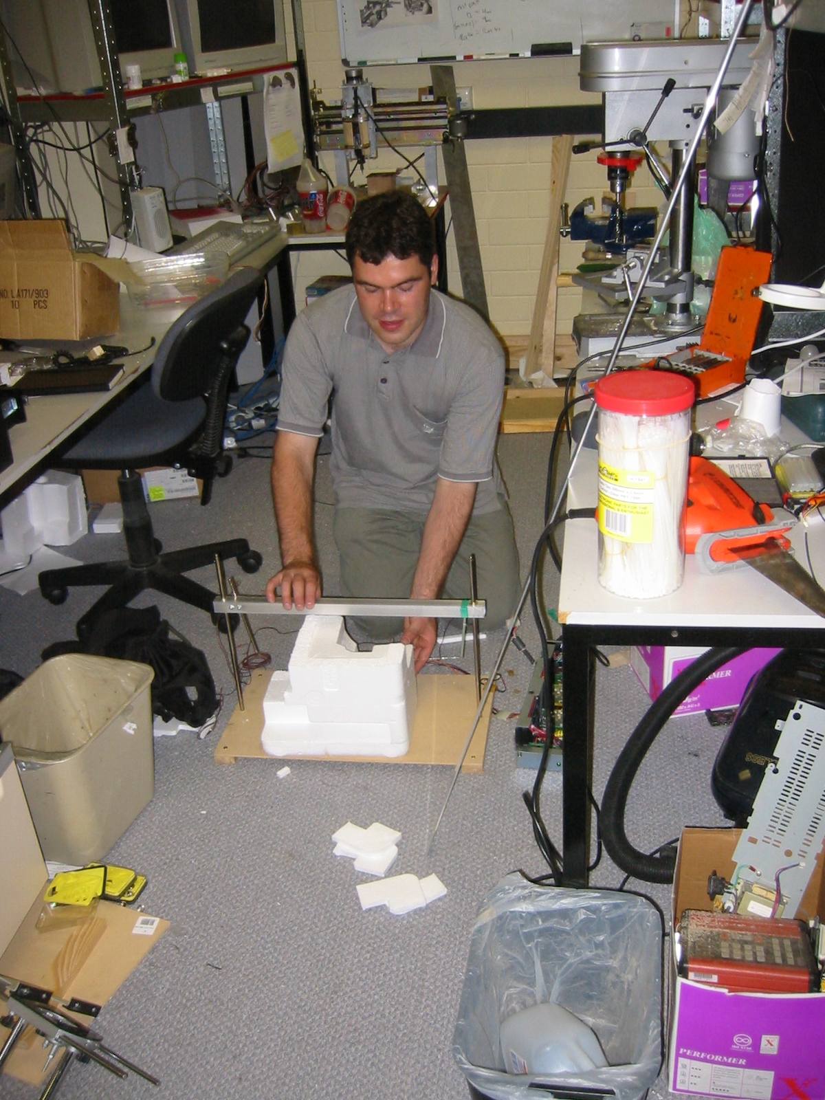
Using the Foam Cutter

|
|
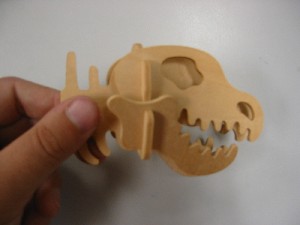
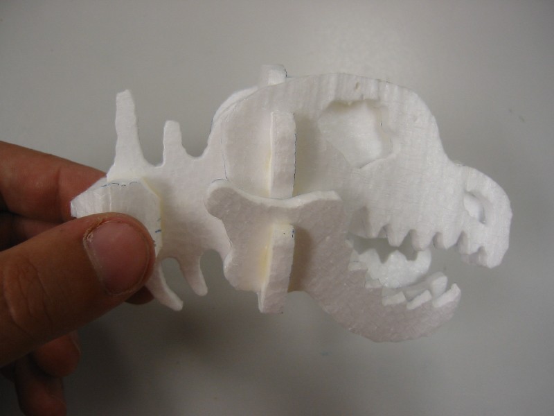
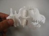
So a friend of mine Ross immediately suggested that we try
cutting one of those wooden model / toy dinosaurs out of
foam. Actually he suggested that we cut it out of foam and
then try pouring it in aluminium with a lost foam process
this weekend. Ross is known for these sorts of cool and
slightly eccentric sort of ideas.
|
|
|
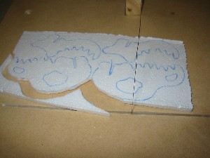
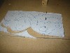
So I used some packing foam that a monitor was shipped in. I
the foam into blocks small enough to feed to the hot wire
foam cutter with a hack saw. Those blocks were then
measured, marked, and cut into sheets of foam. I then
marked out the outline of the pattern of the various pieces
and then and cut out and assembled the pieces. The total
construction time was about 40 minutes and most of that just
experimenting and playing. Another head could likely be
built from scratch in about half the time.
|
Using the Foam Cutter
Hot Wire foam cutting Links to get you started...
Ok, here is a
quick and dirty design
and another
with a cool idea for power
and yet another
basic
design. All look functional and the first two have good
ideas for a rip / guide fence; something that my design lacks.
This site is an excellent resource. His pages walk you through
his hot wire
cut foam research and design process from start to finish in
making high precision foam cut parts for making linear bearings.
Especially look at phase three as it shows his CNC hot wire cutter.