Projector Mount


If you are looking for a reason why you should always keep your mouth shut, look no further. My thesis advisor, Bruce, was talking to Ross asking if he could nock up a projector mount for a project. The projector mount points the projector down onto a table and is used for researching large interactive displays. Eventually we will be able to buy tables with high resolution, millimetre thin, displays embedded into their surfaces. The projector technique is one of the ways we mock up these sorts of user interfaces while we are waiting for the real hardware to arrive.

Any way, Ross told Bruce that he thought he could nock something up in a day or so. At this time I might have coughed and said something about how a real man could have it done in half that time. It was an ill advised comment at best. Ross just smiled at me, then looked at Bruce without missing a beat and said "Aaron is building it". Bruce, always fast on the uptake, just said "Ok" and wandered out of the room. I work with very smart people and boy, do they ever know how to teach you a lesson.

Ok, so after I put this page up I was talking to Ross and he said my recollection was no where near accurate. He thought I had jumped out of my seat to volunteer. His exact wording, which he said I could quote him on, was "you dug your own hole". Which, considering that the projector mount was going to be used for, among other things, a crazy robot tracking project, I probably did. Memory is definitely subjective.

Bruce had another student who had purchased the scaffolding you see to the left in order to mount about 8 cameras pointing at the table as part of a tracking project. Ok if I was going to do this I was going to do it right. Both the position and projection angle were adjustable in my design.

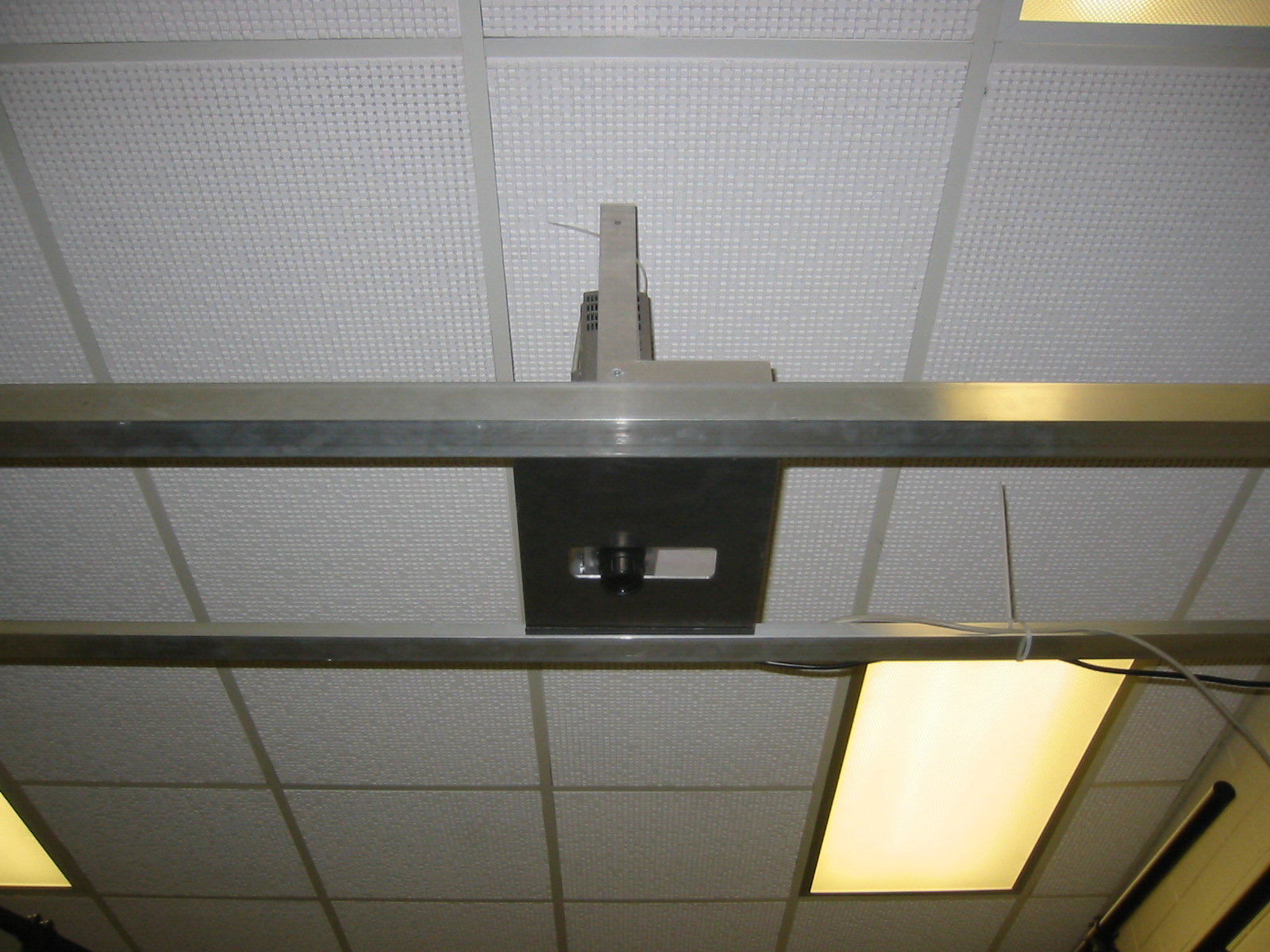
The projector mount sits between two rails bolted to the scaffolding. This actually acted to stabilize the scaffolding. The rails were bolted to a series of convenient mounting holes along the scaffolding. This allowed the mount to be moved, with the rails from "side-to-side" along the scaffolding. Inside the "L" shaped rails the mound was able to be slid "front-to-back" in the grove formed by the rails. I glued stips of rubber cut from old mouse pads to the aluminium plate that formed the base of the mount. This both prevented it from slipping and provided some simple vibration dampening for the projector.

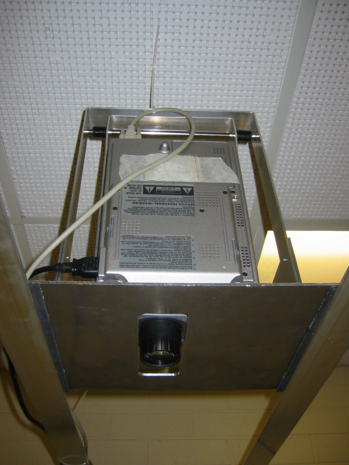
I lathed down a scrap piece of steel rod so that the ends slipped into holes I drilled through a support bar. The bar was a bent piece of aluminium. The lathing let the U shaped support bar capture the steel rod. Then another mount held the camera allowing it so swing on the rod.

Since the mount let the projector swing to adjust the projection angle I needed to mill out a channel in the base so the projector lenses could move freely over the desired range of projection angle.

Ok, so the moral of this story is friends let friends shoot their mouths off then they collaborate to teach that friend a lesson. Thanks guys. The funny part was it took me almost twice as long as Ross's estimate to buy the aluminium, and nock this together. I am not sure of what his intended design was going to be but Ross is the kind of bad ass at this sort of stuff that makes me believe that his implementation would have been better. Ugh, me and my big mouth.