Simple 2 Servo Base


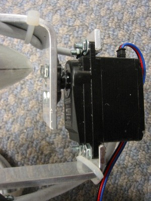
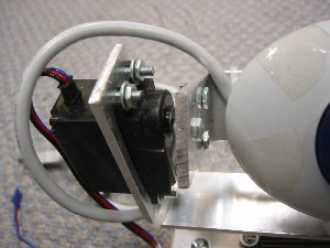
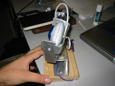
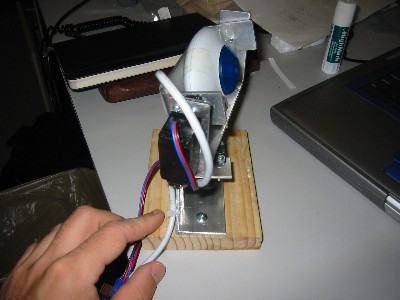
I was hired to build the control circuitry and software for a micro targetable camera base. As part of that development I needed to build myself a targetable camera base to use in software development. I also thought that it would be good way to work out some of the targeting issues I had with my thesis work. Since none of my requirements on the base constrained its size I decided to make it a little more rugged then was probably needed; using thicker bar stock then I have in the past and adding a saddle with support on either side of the rotated base as opposed to just an L shaped support.

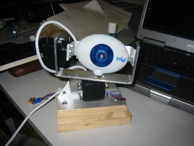
This is a very simple design and came together in somewhere between 6 and 8 hours. A lot of that time however was spent figuring out how I wanted to build it and researching servo motors. If you set out to build exactly this design from scratch you could probably put it together between 1.5-3 hours of solid work with just a hacksaw, ruler, drill, and files. The parts all cut out quickly but filing to your marks takes time.

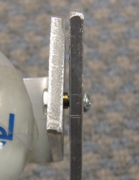
The design is simple and breaks down into two pieces; a saddle and base. Since this is a pretty common and simple design I do not think it needs plans.

Components


Saddle Servo

The saddle has two a U-shaped piece of flat 3mm x 1.5cm Aluminium stock. The outer bar has a channel cut into it to mount the servomotor.

Saddle Bushing

Opposing the Servomotor a screw joins the outer and inner saddle. The screw is 1/8 inch but the hole was over drilled and two small pieces of brass tubing are press fit, one each, into the holes in the outer and inner saddle piece forming bushings. The brass will wear against the steel of the screw better then the Aluminium would. The brass bushing from the inner saddle can be seen in the photo left. The inner pushing is made slightly longer to space the inner and outer saddle arms and prevent them from rubbing.

Base Servo

The part I really do not like about this design is that the load is placed directly up on the servos and their little plastic gear boxes. That frustration is what lead me to build the bases discussed elsewhere on my home pages. This saddle design is an improvement over the L shaped design in that respect as the other side of the arm is pinned taking up part of the load the base however takes the right in the gearbox. The bigger the design the bigger the moment arms for off axis acceleration and the worse the problem when it moves. Still since I don't know what the failure times are going to be here for light loads it might outlast my use of the base even with the shorter life.