Categories
esp8266

Espressif’s “ICACHE_FLASH_ATTR” and larger flash sizes

Just noticed this description on the espressif website describing the
location of the ICACHE_FLASH_ATTR functions in memory.

It looks like methods WITHOUT the ICACHE_FLASH_ATTR marker get cached to memory in 32KB of ram in iram1_0_seg at power up. Methods with “ICACHE_FLASH_ATTR” are located in irom0_0_seg.

Thats the opposite of the behavior I was expecting. However looking in the eagle.app.v6.ld linking script (version esp_iot_sdk_v1.4.0/ld/eagle.app.v6.ld) we see:

MEMORY
{
dport0_0_seg : org = 0x3FF00000, len = 0x10
dram0_0_seg : org = 0x3FFE8000, len = 0x14000
iram1_0_seg : org = 0x40100000, len = 0x8000
irom0_0_seg : org = 0x40240000, len = 0x3C000
}

which is a layout change from the older memory layout found in esp_iot_sdk_v0.9.5/ld/eagle.app.v6.l

MEMORY
{
dport0_0_seg : org = 0x3FF00000, len = 0x10
dram0_0_seg : org = 0x3FFE8000, len = 0x14000
iram1_0_seg : org = 0x40100000, len = 0x8000
irom0_0_seg : org = 0x40240000, len = 0x32000
}

I’m using a few different esp8266 modules, but developing code on a HUZZA board. Checking its flash
I get:

/opt/esptools/esptool-new/esptool.py –port /dev/tty.usbserial-A600dRM4 flash_id
Connecting…
Manufacturer: c8
Device: 4016

Which from what I am seeing online should translate to a Winbond W25Q32 flash chip.

More specifically this list of flash-ROM IDs says that 0x4016 could map to a few devices but both the Windbond device, or the Gicgadevices (based on Maucacture code), are 32Mb devices, so there should be 4MB of flash available which is not reflected in the limits above.

Checking the newer linker scripts, the espressif SDK provides ./esp-open-sdk/sdk/ld/eagle.app.v6.new.2048.ld with a bigger definition.

MEMORY
{
dport0_0_seg : org = 0x3FF00000, len = 0x10
dram0_0_seg : org = 0x3FFE8000, len = 0x14000
iram1_0_seg : org = 0x40100000, len = 0x8000
irom0_0_seg : org = 0x40201010, len = 0xE0000
}
Categories
esp8266

ESP8266 and “rst cause:2”

So programming the esp8266 through a USB FTDI chip that also supplies the 5V rail, means the chip has less than the 500mA provided by the USB buss. There is probably ~450mA left to power and program the ESP. Based on the data sheets that should be more than enough. Turns out it isn’t.

Apparently writing to flash on the esp8266 has higher power transients than can be supplied by USB alone. I added additional capacitive bypassing on the power rails of two 10uF capacitors to help with high current transients, and powered the board off of an external supply. Doing that and reflashing got my example code working and stopped the flash problems. It definitely stopped the “rest cause:2” resets I was seeing.

Categories
esp8266

Espressif reset codes

Looks like there is more to the reset and crash bugs. List of reset causes found on espressif website (http://bbs.espressif.com/viewtopic.php?t=563)

reset cause 1: normally during a Power-On-Reset or by CHIP_PD transient
reset cause 2: normally during a reset caused by a nRESET transient
reset cause 4: normally during a reset by wdt reset

Categories
esp8266

Esp8266 error: “don’t use rtc mem data”

Update: Turns out my problems, while repeatable, were likely to do my libraries being set in a non-homogeneous state. It appears that an auto partially rolled back the SDK version being used, which was weird. A full make clean, and rebuild fixed the problem I was having. Still the reset problem is fairly common with the ESPs and Espressif SDK. This guy summed it up the ESP Reset Problem really well.

So this error was a beast to find – and I saw some others online were having the same problem – so I figured I should post about it someplace Google could find it.

I’m using the espressif development tools, which are getting better, but remain only sparsely documented. My problem started after a change in my code started the ESP crashing on power up. The crash presented, or so I thought, like a flash write error contaminating the boot loader.

I was getting this error about messing with RTC memory:


r
ets Jan 8 2013,rst cause:2, boot mode:(3,6)

load 0x40100000, len 29920, room 16
tail 0
chksum 0x07
load 0x3ffe8000, len 924, room 8
tail 4
chksum 0xbf
load 0x3ffe83a0, len 4528, room 4
tail 12
chksum 0xde
csum 0xde
don’t use rtc mem data

Well, it turns out the problem was my starting to use the init_done_callback code when I upgraded SDK versions. I jumped from a 1.x SDK to a 1.4. The init_done_callback code was added into the SDK somewhere in that range. The call works fine, and I had been using it for a while in my code when I ran into problems merging the timer code. It is not in the documentation anywhere yet, but you apparently can’t mess with the os timers within the init_done_callback function.

Since it looks like init_done_callback is how you launch code after all the underlying espressif code has finished I’m thinking this is a bug. For now I’m going to change to launching my timers before setting the callback, and use a flag to wait until espressif init’s done.

Here’s a cut down version of the code triggering the problem:

void ICACHE_FLASH_ATTR user_init(void){
user_gpio_init();
user_uart_init();

// Problem killing the timer is here! I should handle timers outside callback.
system_init_done_cb(init_done_callback);
}

void init_done_callback(void)
{
// Callback launches fine – but its the setting of os_timers that triggers
// the crash / messing with timer memory error.
start_keepalive_timer(KEEPALIVE_INTERVAL_SECS);
}

void ICACHE_FLASH_ATTR start_keepalive_timer(int interval)
{
#ifdef DBG_KEEPALIVE
os_timer_disarm( &dbg_keepalive_timer);
os_timer_setfn( &dbg_keepalive_timer,
(os_timer_func_t *)dbg_keepalive_timerfunc,
NULL);
os_timer_arm(&dbg_keepalive_timer, (1000 * interval), 1);
#endif
}

Categories
BrightLeaf I am going to try Science!

Fun with data!

So lately I have been playing with data measuring light levels throughout the day. I am fascinated With just how much my brain and eyes filter and smooth my perception of light, making me unaware of startlingly large changes.

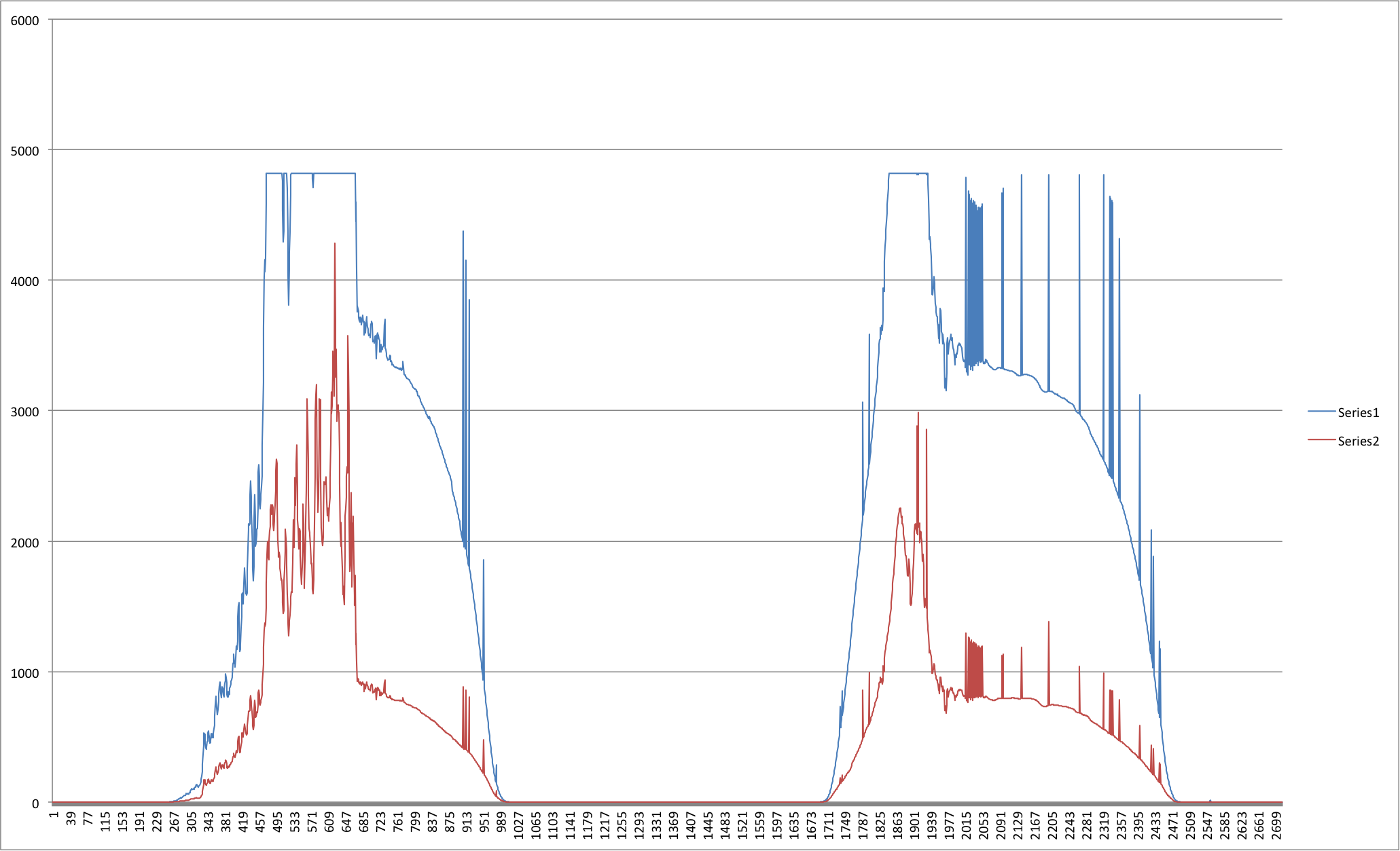
This graph shows data taken from the same light sensor sampling over two days. The red series of data reflects UV light levels, and the blue reflects UV + Visible light levels.

sensor_id85_day2

Two back-to-back days can vary in duration by 40 minutes! Sure sunrise and sunset times between two days only change slightly, but cloud cover and weather has a massive impact on the light profile of the day. During darkening leading up to sunset the brightness can halve every seven-minute for two hours without it being noticeable!

Some data is just fun to play with.