Categories
esp8266

Espressif’s “ICACHE_FLASH_ATTR” and larger flash sizes

Just noticed this description on the espressif website describing the
location of the ICACHE_FLASH_ATTR functions in memory.

It looks like methods WITHOUT the ICACHE_FLASH_ATTR marker get cached to memory in 32KB of ram in iram1_0_seg at power up. Methods with “ICACHE_FLASH_ATTR” are located in irom0_0_seg.

Thats the opposite of the behavior I was expecting. However looking in the eagle.app.v6.ld linking script (version esp_iot_sdk_v1.4.0/ld/eagle.app.v6.ld) we see:

MEMORY
{
dport0_0_seg : org = 0x3FF00000, len = 0x10
dram0_0_seg : org = 0x3FFE8000, len = 0x14000
iram1_0_seg : org = 0x40100000, len = 0x8000
irom0_0_seg : org = 0x40240000, len = 0x3C000
}

which is a layout change from the older memory layout found in esp_iot_sdk_v0.9.5/ld/eagle.app.v6.l

MEMORY
{
dport0_0_seg : org = 0x3FF00000, len = 0x10
dram0_0_seg : org = 0x3FFE8000, len = 0x14000
iram1_0_seg : org = 0x40100000, len = 0x8000
irom0_0_seg : org = 0x40240000, len = 0x32000
}

I’m using a few different esp8266 modules, but developing code on a HUZZA board. Checking its flash
I get:

/opt/esptools/esptool-new/esptool.py –port /dev/tty.usbserial-A600dRM4 flash_id
Connecting…
Manufacturer: c8
Device: 4016

Which from what I am seeing online should translate to a Winbond W25Q32 flash chip.

More specifically this list of flash-ROM IDs says that 0x4016 could map to a few devices but both the Windbond device, or the Gicgadevices (based on Maucacture code), are 32Mb devices, so there should be 4MB of flash available which is not reflected in the limits above.

Checking the newer linker scripts, the espressif SDK provides ./esp-open-sdk/sdk/ld/eagle.app.v6.new.2048.ld with a bigger definition.

MEMORY
{
dport0_0_seg : org = 0x3FF00000, len = 0x10
dram0_0_seg : org = 0x3FFE8000, len = 0x14000
iram1_0_seg : org = 0x40100000, len = 0x8000
irom0_0_seg : org = 0x40201010, len = 0xE0000
}
Categories
esp8266

ESP8266 and “rst cause:2”

So programming the esp8266 through a USB FTDI chip that also supplies the 5V rail, means the chip has less than the 500mA provided by the USB buss. There is probably ~450mA left to power and program the ESP. Based on the data sheets that should be more than enough. Turns out it isn’t.

Apparently writing to flash on the esp8266 has higher power transients than can be supplied by USB alone. I added additional capacitive bypassing on the power rails of two 10uF capacitors to help with high current transients, and powered the board off of an external supply. Doing that and reflashing got my example code working and stopped the flash problems. It definitely stopped the “rest cause:2” resets I was seeing.

Categories
esp8266

Espressif reset codes

Looks like there is more to the reset and crash bugs. List of reset causes found on espressif website (http://bbs.espressif.com/viewtopic.php?t=563)

reset cause 1: normally during a Power-On-Reset or by CHIP_PD transient
reset cause 2: normally during a reset caused by a nRESET transient
reset cause 4: normally during a reset by wdt reset

Categories
esp8266

Esp8266 error: “don’t use rtc mem data”

Update: Turns out my problems, while repeatable, were likely to do my libraries being set in a non-homogeneous state. It appears that an auto partially rolled back the SDK version being used, which was weird. A full make clean, and rebuild fixed the problem I was having. Still the reset problem is fairly common with the ESPs and Espressif SDK. This guy summed it up the ESP Reset Problem really well.

So this error was a beast to find – and I saw some others online were having the same problem – so I figured I should post about it someplace Google could find it.

I’m using the espressif development tools, which are getting better, but remain only sparsely documented. My problem started after a change in my code started the ESP crashing on power up. The crash presented, or so I thought, like a flash write error contaminating the boot loader.

I was getting this error about messing with RTC memory:


r
ets Jan 8 2013,rst cause:2, boot mode:(3,6)

load 0x40100000, len 29920, room 16
tail 0
chksum 0x07
load 0x3ffe8000, len 924, room 8
tail 4
chksum 0xbf
load 0x3ffe83a0, len 4528, room 4
tail 12
chksum 0xde
csum 0xde
don’t use rtc mem data

Well, it turns out the problem was my starting to use the init_done_callback code when I upgraded SDK versions. I jumped from a 1.x SDK to a 1.4. The init_done_callback code was added into the SDK somewhere in that range. The call works fine, and I had been using it for a while in my code when I ran into problems merging the timer code. It is not in the documentation anywhere yet, but you apparently can’t mess with the os timers within the init_done_callback function.

Since it looks like init_done_callback is how you launch code after all the underlying espressif code has finished I’m thinking this is a bug. For now I’m going to change to launching my timers before setting the callback, and use a flag to wait until espressif init’s done.

Here’s a cut down version of the code triggering the problem:

void ICACHE_FLASH_ATTR user_init(void){
user_gpio_init();
user_uart_init();

// Problem killing the timer is here! I should handle timers outside callback.
system_init_done_cb(init_done_callback);
}

void init_done_callback(void)
{
// Callback launches fine – but its the setting of os_timers that triggers
// the crash / messing with timer memory error.
start_keepalive_timer(KEEPALIVE_INTERVAL_SECS);
}

void ICACHE_FLASH_ATTR start_keepalive_timer(int interval)
{
#ifdef DBG_KEEPALIVE
os_timer_disarm( &dbg_keepalive_timer);
os_timer_setfn( &dbg_keepalive_timer,
(os_timer_func_t *)dbg_keepalive_timerfunc,
NULL);
os_timer_arm(&dbg_keepalive_timer, (1000 * interval), 1);
#endif
}

Categories
esp8266 Projects

Pythagorean Plotter, 4-day Hacking Session

When some of my friends come to town to visit we go see the sites, which is fun. Others though come to town and we spend the entire visit on a hacking session broken up with beer drinking and bad movies. My friend Phil’s is in town for such a visit – and we are doing a 4-day hacking session building a wall plotter. We are calling the plotter Wilbur.

The unique part of our wall plotter is we are building it around industrial suction cups. Our goal is to be able to sneak into a friend’s office, or up to a window, and suction cup the plotter onto the white board or window. The goal is a stealth graffiti system for pranks on friends.

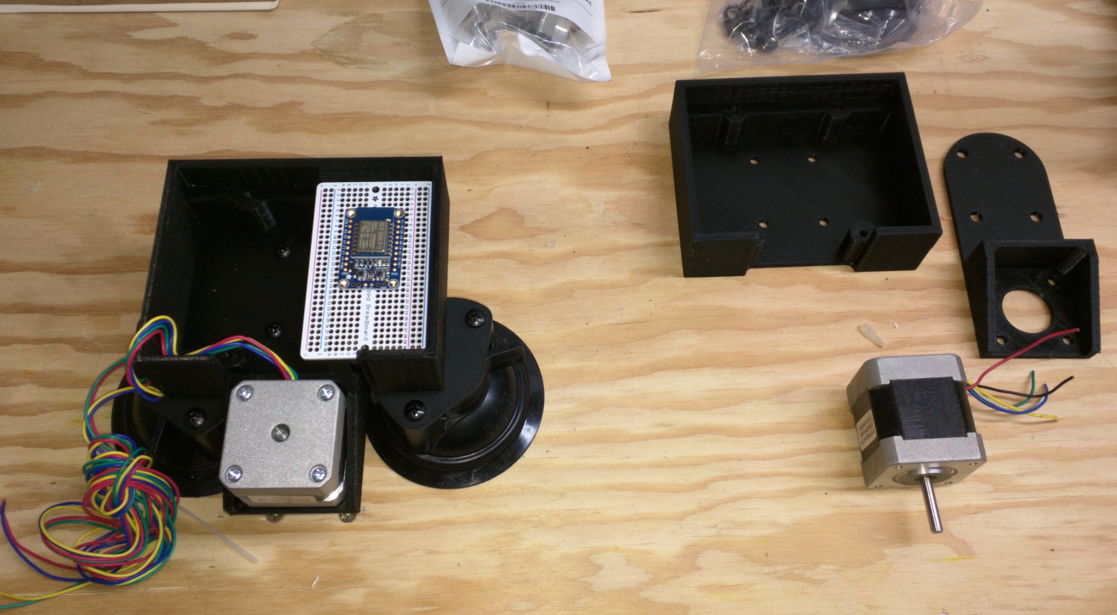
In preparation for Phil hitting town I ordered up some RAM double suction cup mounts, and then CAD modeled up a case coupling the mechanical elements to the stepper motor mounts.

Wilbur_Ploter_Day1_Mechanical_P1

I split the design into two parts so that would bolt together, and to the underlying RAM mount. The electronics are fairly simple, and esp8266 to handle WiFi and computing, and another stepper driver board for handing the motor. Since we are using a counterweighted design all we need to be able to do is control the direction and stepping of each motor, as well as provide pen up / down commands. From those simple pieces we should be able to build a system with very complex output.

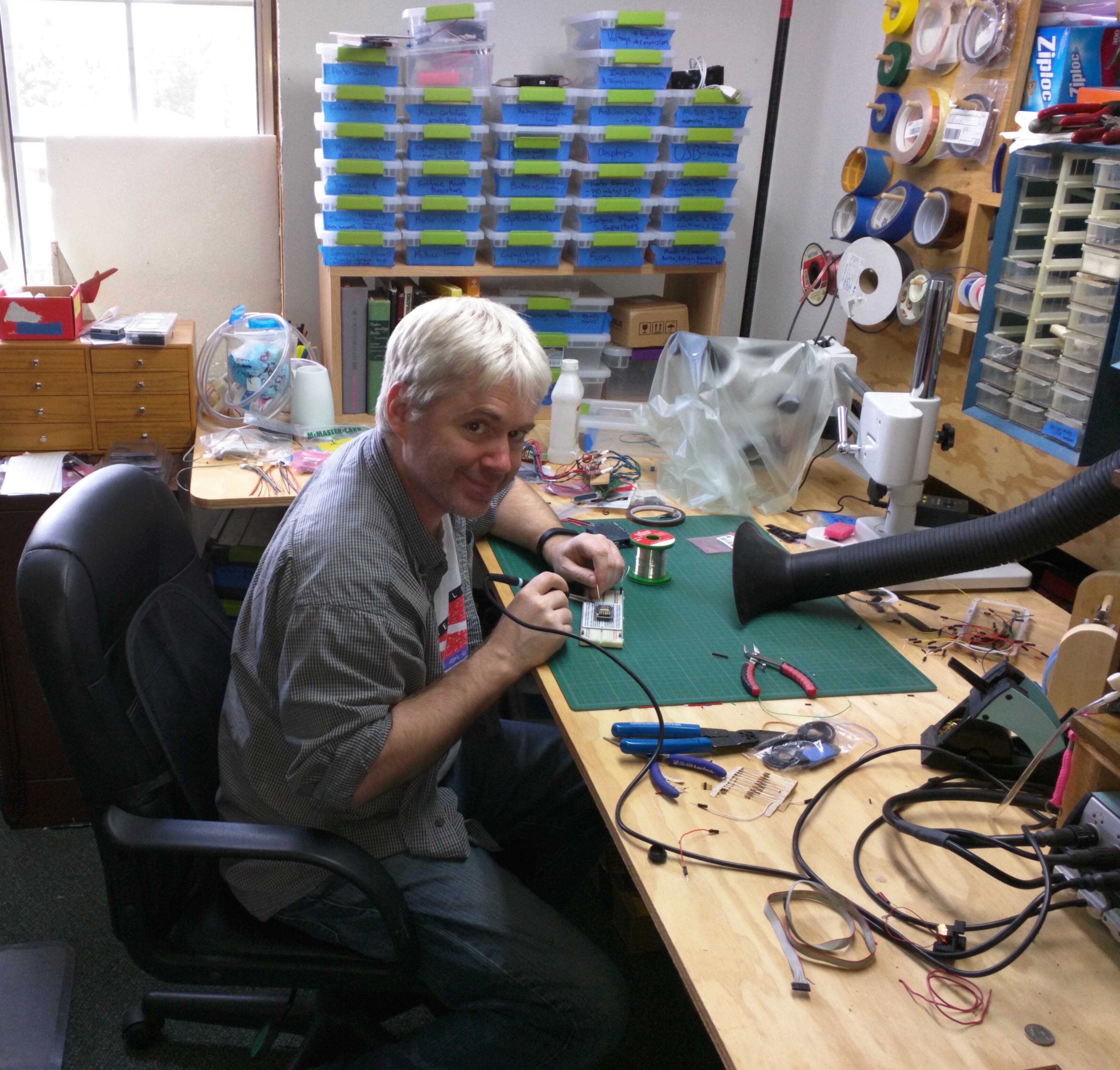
The required action shot. Phil soldering. Which reminds me – he’s actually coding while I write this, so I better get back to it.

Phil_Soldering_FallVisit_Day1

Categories
BrightLeaf esp8266 Startup Ideas

Packaging a startup evaluation prototype!

I’m in the process of prototyping several IoT devices as part of evaluating a startup idea, and since the devices are going to go in people’s homes design matters – even for initial units for evaluating the idea. Actually, I think design is especially important for evaluation units because I am trying to find out if people want to bring technology like this into their homes.

One of the things that make me love 3D printers is that they make the black project boxes a thing of the past. Once I finished prototyping the electronics, firmware, and cloud side code – I was able to sketch up a few case designs on paper. Then pick the one I liked the best for initial testing.

WP_20150509_002

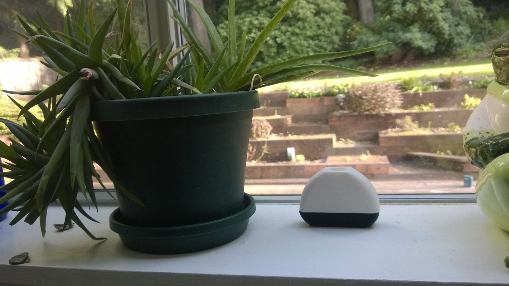
At this point I should probably point out that I am not an industrial designer. When I showed my design to the designer I want to work with on the project, he said it reminded him of one of those bubble gum tape dispensers from when we were kids. (Ouch!) Still, I think my design is a hell of an improvement over testing with black project boxes, and it’s a pretty decent match for the design I liked best of the 15 or so I sketched through. Here is what it looks like sitting on the windowsill in my reading room.

Brightleaf_V1_testing

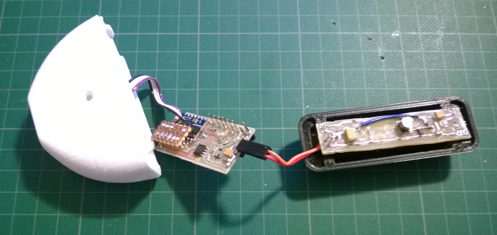
I have the design split across three boards. A sensor board inside the dome, the eps8266 board with sensor breakout, and a DC/DC converter to power everything off of a AAA battery. The boards I made at home are super ugly, and hacked on, but functional. Enough that I am ready to put in an order for an initial run of boards to build a dozen or so test units.

Brightleaf_V1_open

Categories
esp8266

Prototyping a product with the esp8266

I’m building some proof of concept prototypes for a startup product around the ESP’s, and they proved quick and easy to iterate around. This stuff just used to be so much harder! It is awesome to have an 80MHz 16 bit micro-controller with built in WiFI for $3. The ESP-03’s I have been using are also nicely packaged into an easy to use breakout board.

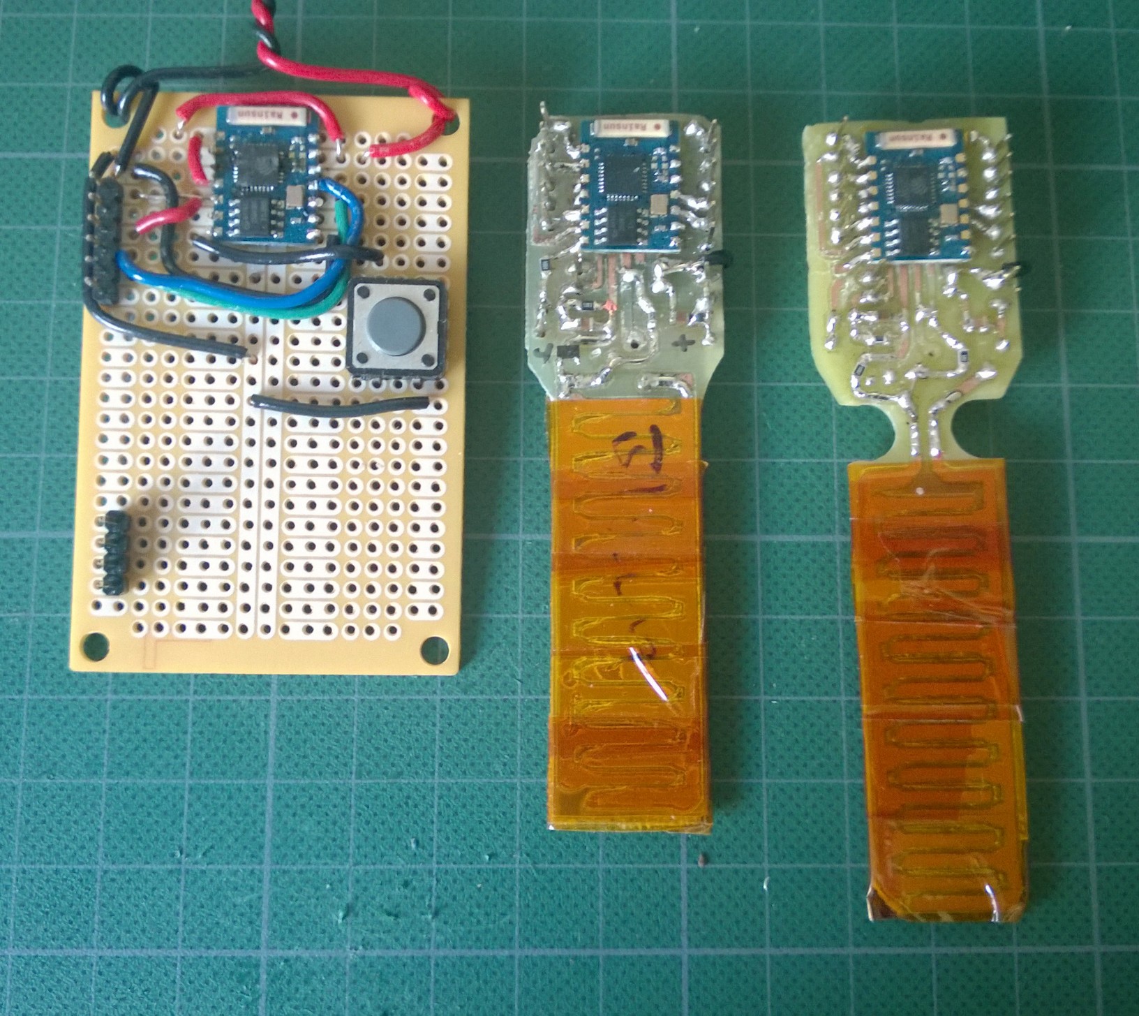
This picture pretty much captures my route so far. I had just heard about Radio Shack’s being broken up when my ESPs arrived. So I used a Rat Shack breakout to test the core circuit, then iterated my design on some quick and dirty home cut PCB boards. Forgive the nasty look of the soldering, each of those boards has been hacked on a bunch as I iterated through different sensor circuits. The end result turned out to be a nice proof of concept prototype, enough for me to evaluate the startup idea. Well, enough that I could figure out I want to make a run of ~100 of these units and get them in the hands of others to do more evaluation.

soil_sensor_iteration

You know that saying that single men are bears with furniture? Well, for me at least its true. You can ask my house plants which I am always forgetting to water. So I wanted a network connected soil moisture sensor to remind me about watering specific plants. The other sensors on the board are for a project I am evaluating with some friends as a startup idea. That circuit sits, mostly, on a separate daughter board not shown.

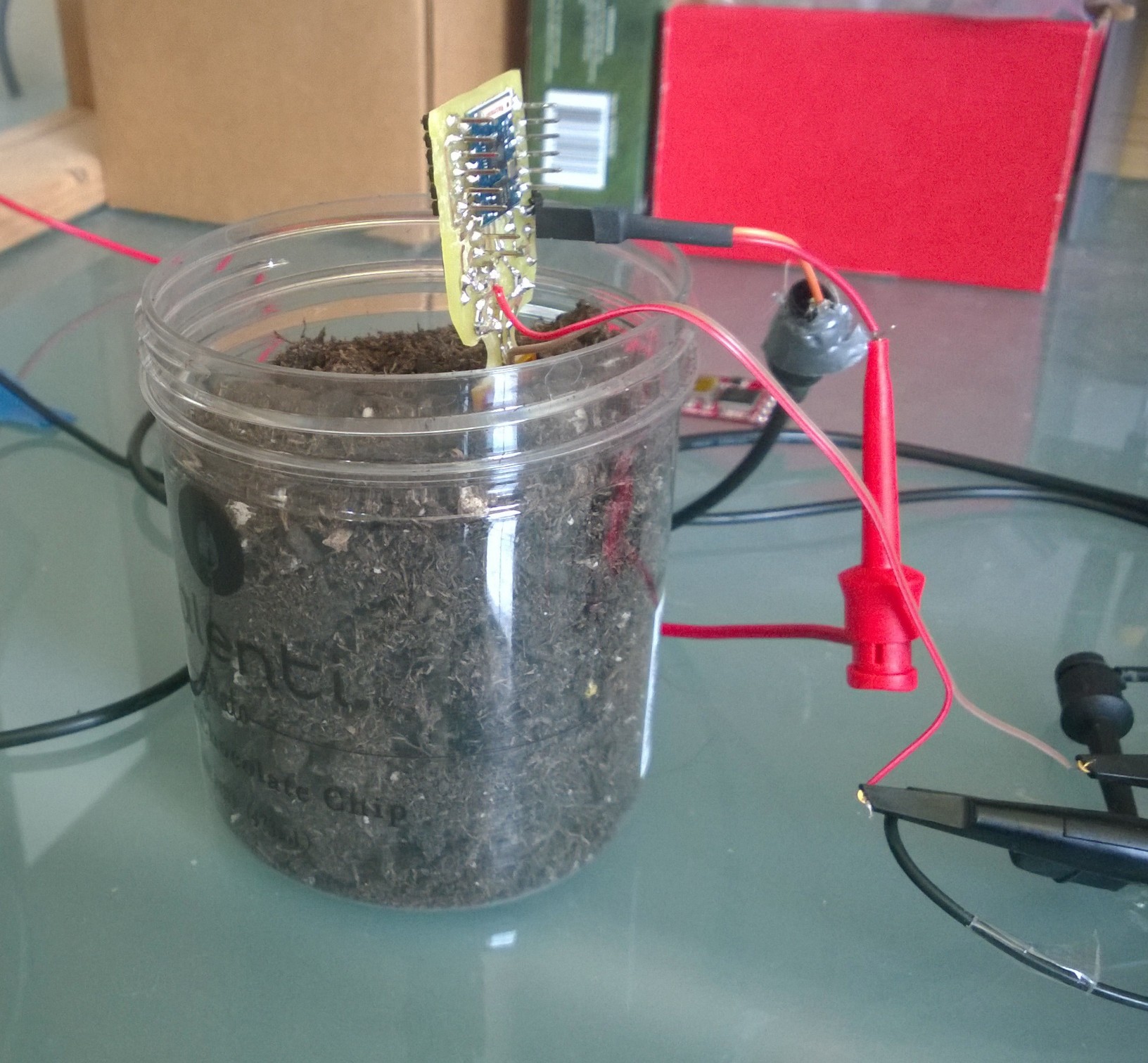
Here you can see the soil moisture sensor being tested.

testing_soil_sensor

So while I love the ESP’s, and intend to blog more about them – it is a bit of a love / hate relationship. I have a pile of blown boards. The first one I blew I chalked up to my being the cause, but after a few of them I’ve noticed that the chips in the batch I bought seem to be highly sensitive to reprogramming cycles. It looks like the number of read / write cycles on some of the chips internal flash might be as low as 10-15 cycles. Once I have some more time I intend to try thrash testing them to nail down failure parameters better.

Categories
esp8266

ESP8266 Breakout Board Versions

This URL has a great roundup of all the current EPS breakout boards, with pictures for easy identification.

esp8266 Breakout Board Hardware Roundup